The TR1985 Transceiver
made by STC
|
|
This equipment, operating
in the aircraft AM band from around 100MHz to 125MHz, was used
in aircraft like the English Electric Canberra for air-ground
communications. It would have been the type of set that the last
of the R1392 control tower receivers would
have picked up. It represents the sort of lengths that designers
had to resort to without the benefit of synthesised tuners, varactor
diodes and broadband amplifiers. Nowadays a pilot has to merely
flick a few switches and a transmitter or receiver will be ready
for use without the requirement for mechanical aids. |
 |
|
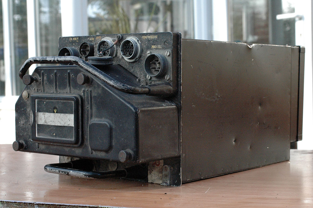
The picture above shows a brand new commercial version
of the TR1985, The S.T.R.9 with its control box
Here are some pictures of my military set... note
the additional "AUX" connector and panel for inserting
notes
|
 |
|
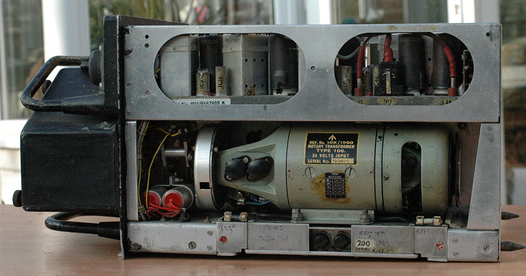
Side view showing the
dynamotor. 24 volts input, 250 volts and neg 50 volts output. |
 |
|
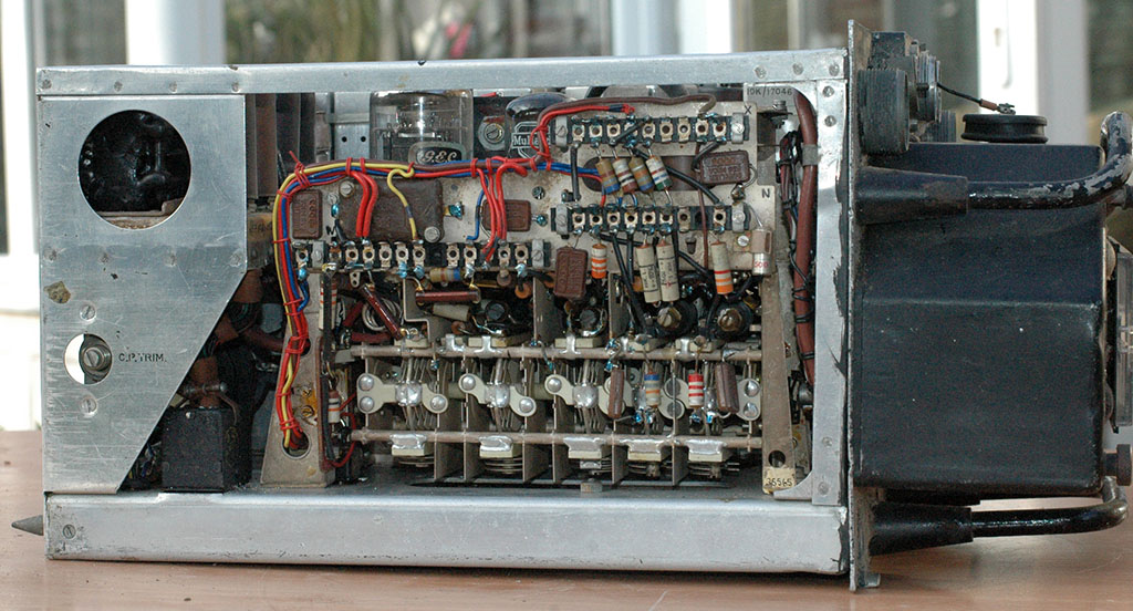
The opposite side showing the transmitter module
with its B9G QV04-7 driver and TT15 PA.
Carbon pile trimmer control on the left side.
|
 |
|
The valve chart and
the mod record indicating 18 modifications incorporated |
 |
|
Top view showing the various plug-in modules.
Top=9.72MHz IF strip, left = transmitter amplitude
modulator, centre =receiver, bottom=transmitter
|
 |
|
Bottom view showing the trimmers for the transmitter
and receiver; aerial relay on left.
The diecast box covers dynamotor circuitry.
|
 |
|
Front view with cover removed showing a complete
set of crystals.
Were these being used immediately before the set
was demobbed?
|
 |
|
A closer view followed
by a table listing the frequencies in use, some of which are
very odd if my calculations are correct? |
 |
|
The crystal is multiplied by 18 (x3 x3 x2) and mixed
with the incoming signal to produce an IF of 9.72MHz
The oscillator multiplier output of x9 is added to
a crystal oscillator output of 4.86MHz and the result multiplied
by two to derive the transmit frequency.
|
|
Channel |
Crystal |
Rx mult |
RECEIVE |
Tx out |
Tx local osc |
TRANSMIT |
|
1 |
5055 |
90990 |
90999.72 |
45495 |
45499.86 |
90999.72 |
|
2 |
6380 |
114840 |
114849.72 |
57420 |
57424.86 |
114849.72 |
|
3 |
8200 |
147600 |
147609.72 |
73800 |
73804.86 |
147609.72 |
|
4 |
8428 |
151704 |
151713.72 |
75852 |
75856.86 |
151713.72 |
|
5 |
5055 |
90990 |
90999.72 |
45495 |
45499.86 |
90999.72 |
|
6 |
5333.75 |
96007.5 |
96017.22 |
48003.75 |
48008.61 |
96017.22 |
|
7 |
5380 |
96840 |
96849.72 |
48420 |
48424.86 |
96849.72 |
|
8 |
7440 |
133920 |
133929.72 |
66960 |
66964.86 |
133929.72 |
|
9 |
7860 |
141480 |
141489.72 |
70740 |
70744.86 |
141489.72 |
|
10 |
8440.91 |
151936.38 |
151946.1 |
75968.19 |
75973.05 |
151946.1 |
|
|
Can anyone explain the odd results
in the above table? Is it possible one of the two multipliers
is working at x2, x3 or x4 depending on the crystal frequency?
Or is it simply that the last owner plugged in a set of crystals
at random and only two were valid, as the manufacturer specified
for the TR1985, a range of 5015 to 6404KHz?
Higher frequency variants used
crystals up to 8126.67KHz. |
|
The TR1985 was tuned from
a remote control box... giving the impression that it was a simple
matter to change frequency. However it required the benefit of
a motor driven set of levers and switches to achieve the end
result. Firstly a crystal, cut for the particular selected frequency,
has to be selected, secondly the tuning capacitor for the receiver
front-end and heterodyne oscillator had to be adjusted and thirdly
the corresponding tuning capacitor in the transmitter needed
adjustment. All the necessary mechanical settings were made at
the time a new crystal was plugged in.
By a clever clutch and gearbox
arrangement the work of tuning and switching was carried out
by the same dynamotor used for the HT and grid bias supplies
to the tx and rx. This brings me to another of the disadvantages
of equipment used in the early days of the cold war. Not having
the benefit of transistors, the 21 valves needed a sizeable power
input just to get them up to temperature so they'd work. They
would then demand high voltages for their anode and screen supplies.
The inefficiency of a set such as the TR1985 was considerable,
not to mention the weight.
If numbers mean more to you
then how about 210 watts input to provide 4 watts of RF output
and it weighed in at around 25 pounds or nearly 12kgm. |
 |
The 21 valve line-up for
the set can be seen in the picture and is as follows:-
Transmitter (LHS): CV4014 X
2, CV4063 X 2, CV483, CV4046
Receiver (centre): CV4063 X
2, CV4014 X 3
IF strip(RHS): CV4015 X 3, CV4025,
CV4059, CV4014
Modulator(rear): CV4015, CV4063,
CV4058 X 2
In commercial terms these are
high quality versions of the EF91 (M8083/CV4014), EL91 (M8082/CV4063),
QV04-7 (M8157/CV483), TT15 (CV4046), EF92 (M8161/CV4015), EB91(M8079/CV4025),
EAC91(M8097/CV4059), EC90(M8080/CV4058) |
|
|
Another problem of course,
concerning equipments of the valve era, was reliability. Valves
have a finite life and with a collection of 21 of the pesky blighters,
it wouldn't be long before emissions would start dropping off,
demanding a visit to the workshop for servicing. A hidden bonus
is that repeated visits for servicing allowed modifications to
be made. This set carries a mod plate with 18 of its 25 struck
off, no doubt reflecting design improvements, changes to specification
and the fitting of alternative components etc. The only date
stamp visible (on the rear of the chassis) is "Sept 1980".
Is this the date it was finally stood down or does the adjacent
red "R" merely mean it had been further repaired and
put back into service?
The outer case is made from
aluminium and the framework inside from the same material. The
various demountable chassis are quite heavy, being made from
brass, plated with what looks like cadmium.
Considerable effort has been
made to aid the servicemen by giving all the units plug and socket
connections, allowing replacement in the event of damage or failure.
Worth a mention is the regulator for
the valve heaters. This is a carbon pile regulator and its principle
dates back to the earliest days of electric lighting.
In the days before high power tungsten
or carbon filament lamps a carbon arc was used in places like
theatres. The difficult part of using a carbon arc was dealing
with electrode wear so a solenoid regulator was developed which
used current consumed by the lamp to set the relative position
of the carbon electrodes. More current pulled the arc apart and
less let the carbons move closer together, thus maintaining a
constant light output as the electrodes were used up.
The principle of the carbon pile regulator
is similar. You adjust the current through the valve heater circuit
by setting a current through a solenoid which is mechanically
coupled to the carbon pile and having done this any increase
in voltage will release pressure on the carbon sections making
up the pile, increasing their resistance. A decrease in voltage
will press the carbon pile sections together thus reducing their
overall resistance. In this way the 26 volt input voltage from
the aircrafts power unit will not over-run the valve heaters
if it were to rise and vice versa.
Valve heaters are arranged in three
parallel groups wired in series requiring 3 x 6.3 volts or 18.9
volts. The regulator must therefore drop a nominal 24-18.9 volts
or 5.1 volts.
In the early 60s these equipments provided
an easy way for radio amateurs to sample the delights of operating
on the 2-meter band and I recall with pleasure having many hundreds
of QSOs using the transmitter section (left) of one of these
TR1985s, suitably tweaked and crystalled for the 144-146MHz band.
The PA valve is rated at 25watts, and using AM, provided quite
a potent signal. |
|
In those days (the 1950s and 60s)
most amateurs used AM on 2 metres using one or more crystals
for their transmitter. A typical receiver would be the shack's
HF receiver tuning say 24 to 26 MHz with a 2 metre nuvistor converter
plugged into the aerial socket. Contacts were made by transmitting
on your favourite frequency and indicating you were tuning high
to low or whatever for a reply. A smart operator returning the
call would plug in the appropriate crystal to be heard first.
Having made contact you would retire to the back garden with
the receiver volume turned up and swing your aerial round to
get the best reception. Nowadays VHF operation is much like using
a telephone. |