|
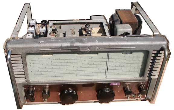
The Eddystone 770R is a VHF receiver
that tunes from the bottom end of the short-wave band to the
VHF marine band. In its day it was probably rarely surpassed
as stability is very good, and its range of features pretty comprehensive...
for the 50s. To make the coil-pack easily manufacturable, and the tuning scale reliably accurate, the set uses a large turret; similar to the ones used in the wartime R206 and the post-war Murphy marine receivers. |
|
|
 |
|
|
|
 |
 |
|
|
|
 |
|
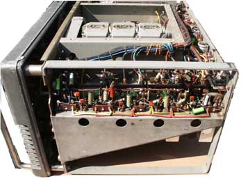
The Eddystone turret carries three
coils per range. As it has six ranges the number of coil packs
is 18. For some reason, best known to the Eddystone engineers,
the coils can only be adjusted in-situ after first removing the
adjacent set. This is not the only shortcoming. Another is the
fact that the IF coil lower slugs can only be adjusted by threading
the adjusting tool between close-packed components under the
chassis. As some of the obstructions are at HT potential a metal
stemmed adjusting tool must first be insulated. The set was still relatively deaf. To get enough sensitivity to get this far I'd had to short-circuit the biasing of the first two IF stages. What next? I'd already changed all the brown capacitors in the front end. Once the capacitors in the mixer and oscillator had been replaced, I'd found the highest range was beginning to respond to signals. At least I could hear the signal generator, whereas previously I couldn't as I'd suspected the oscillator wasn't oscillating. During the work I'd noticed that flexing the cans of the middle IF transformers had increased sensitivity quite dramatically. One reason was loose pins in the valve sockets, specifically the connection to the screen grid of the fourth stage. The third stage was also intermittent and this turned out to be a dry solder joint at the screen grid of the third IF valve. Changing all the old tubular IF-strip decoupling capacitors, together with the screen grid feed resistor of the last IF stage improved matters yet again. Next a cursory look at the other components in the IF strip... Although most resistors are not particularly critical in valve circuits, I found several that had drifted to almost double their marked values, reducing screen and anode voltages. To be on the safe side I also fitted a new diode detector, using a germanium type, together with a couple of other semiconductor diodes, a couple of resistors and some decoupling capacitors on the audio chassis. The receiver was now producing quite
acceptable results. The worst mechanical fault is wear in the turret tuner selector arrangements. There is a large circular Bakelite, or phenolic, sheet with an ident for a bearing to precisely locate the drum's position. Over the years the hole mating with the bearing has worn so that the drum can be wobbled from side to side. This results in a lack of preciseness to wave changing and results in a degree of resetting error. The wear could be fixed but would necessitate the complete dismantling of the drum and either a repair to the phenolic plate or the fitting of a new one made from the pattern of the old one. Next I looked at a few odds and ends. The RF gain control connects to its knob via a short length of Bowden cable. This had perished resulting in a very springy and imprecise feel in the control. I removed the fittings and made a brass coupler to replace the old type, passing the new quarter inch spindle through the outer part of the old panel fitting. Not perfect but considerably better than before. Once reliable operation had been achieved I checked the accuracy of each of the tuning ranges. All were pretty good with scale markings quite acceptable once the trimmers in the coil packs had been adjusted. Fortunately it was not necessary to remove coil packs to gain access to the slugs in the coils. Possibly this was so because I'd fitted a new padding capacitor in the oscillator in my efforts to sort out the dial discrepancy. There are a number of other areas needing to be checked out. The BFO did actually work during initial testing but stopped working when I got round to finishing off loose ends. The user manual is misleading as it gives the anode voltage of the BFO valve as something between 80 and 55 volts depending on the type of voltmeter one is using. Unfortunately what the quoted voltgae refers to is the tapping point between a 68k and a 22k resistor. The true anode voltage is nearer 15 volts. The main components for the BFO are buried inside a metal can that needed to be removed from the chassis in order to carry out any checks. Several solder points are first dealt with, removing the valve heater supply, anode feed, ground and RF output. After wiring it up on the bench the unit stubbornly refused to oscillate. Initially I confirmed that the internal components where in order; three capacitors,and the 22k and 47k resistors. Next I tested the coil with an old grid dip meter (a real grid dip meter) and found it could be brought to resonance by twiddling the slug in the coil former. Each time I applied power however the thing refused to oscillate until I poked at the coil, whereupon it suddenly started up. Presumably the enamel had perished in some way and had allowed a short to develop? When the BFO had been reassembled and soldered back into the circuit it worked perfectly. The manual suggests it is offset from the 5.2MHz IF frequency by 1000Hz and this was done by setting the drum between bands, injecting a 5.2MHz carrier via the aerial socket and setting the tuning slug for a suitable tone. Before I'd had chance to drip wax into the tops and bottoms of the IF coils to prevent movement of the (very loose) slugs I discovered a tube of Radiospares patent compound which seems to me to be very similar to the sticky substance used in two-part Araldite. I secured the dial pointer with superglue to prevent it wandering again and finally checked the tuning of the IF transformers and the discriminator coil. The latter I achieved using a sweep generator. A note here on IF alignment won't go amiss. It's imperative that the IF tuning is carried out using the CW position of the mode switch and not the other settings. AM provides AGC, which can upset the tuning and both the narrow and wideband FM settings introduce additional coils into the transformers. This is done so that the IF bandwidth can be broadened and any attempt to twiddle coils in the FM settings will ruin AM gain (excepting the discriminator of course which has to be set up in FM). During the alignment procedure I'd noticed that there are three resistors that are switched into the bias circuits of the first couple of IF amplifiers. That for the AM and CW positions is marked in the component listing as "value to be determined". As the value of this resistor has a dramtic effect of overall IF gain I experimented with it and found that a 68ohm component produced a much higher gain than the 220ohm part that was fitted. Any less than 68ohms seemed to introduce excessive noise and some instability. Overall performance is now quite good, especially on the lower wavebands. Band II is quite respectable for an old-timer but the highest band is pretty poor in comparison. I suspect that this is due to deterioration, and subsequent leakiness, of the various parts used in the front-end. Now that I consider myself something of an expert on the 770R, perhaps I'll investigate my own Eddystone. At least mine has a silky smooth tuning mechanism, although I do expect to find precisely the same "stock" faults as I discovered in the customer's example. Oh, and I seem to have acquired another example of this receiver so now I have two in the queue. One of these I'll certainly be selling once it's been sorted out. |
 to find out more about the specification