|
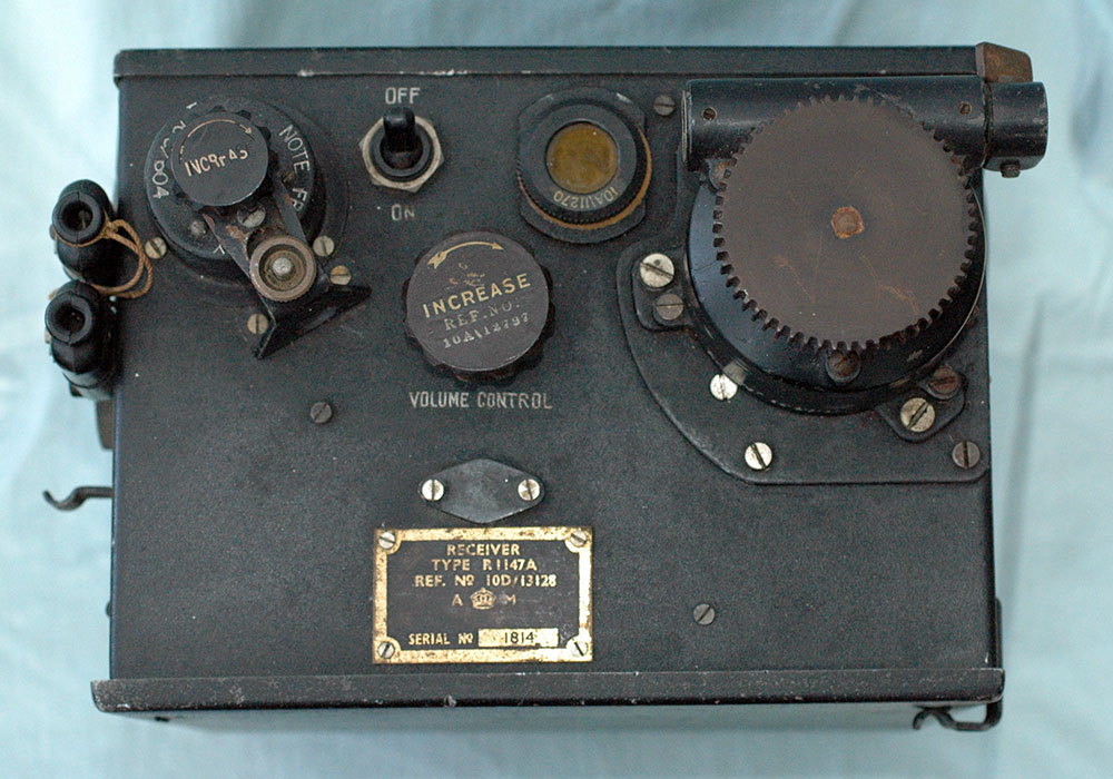
This rather rare radio
was used in various aircraft including the Spitfire and was developed
from a navy equipment loaned to the RAF for letting the pilot
or navigator steer correctly for his base. It replaced the earlier
R1110.
Ordinarily I'd have expected
the aerial for a set such as this could be rotated and thus determine
the direction of a beacon. Usually a null in signal is easier
to detect than a peak although I'm unsure in this application
which method was used. I understand however that this set used
a retractible quarter-wave whip. A clue to its operation might
be inferred by the choice of words "rotating beacon transmitters"
in the technical manual. The beacon station would transmit an
AM signal carrying a supersonic tone. The R1147A can be tuned
to the signal and an audible AF tone peaked by the control on
the upper left which is an adjustable audio frequency coil used
much like a BFO. The R1147 tuneable band extends from 180 to
220Mc/s and is marked on the dial by letters A, B, C and so on.
The other day, Paul Smith down
under contacted me with information on how the R1147 was used
and now everything falls into place. The
brief description is here and an interesting
paper from 1947 can be seen here. The system must have saved
countless aircraft from running out of fuel.
In a single seat aircraft such
as a Spitfire the set could be positioned such that the pilot
could tune the set directly using the toothed ebonite knob. The
set could also be tuned remotely using a duplicate of the geared
mechanism connected by Bowden cable. See
the remote tuner.
I'll need to carry out some
experiments on this set in order to determine exactly how it
works; basically the beacon transmits a tone above the normal
audio range and this is heterodyned or mixed down to an audible
note by turning on a BFO signal via the socket adjacent to the
headphone socket. There is also a remote control connector. See below.
A standard installation used
a power supply box, driven from the aircraft's batteries, carrying
a rotary transformer supplying HT to the receiver. |
 |
|
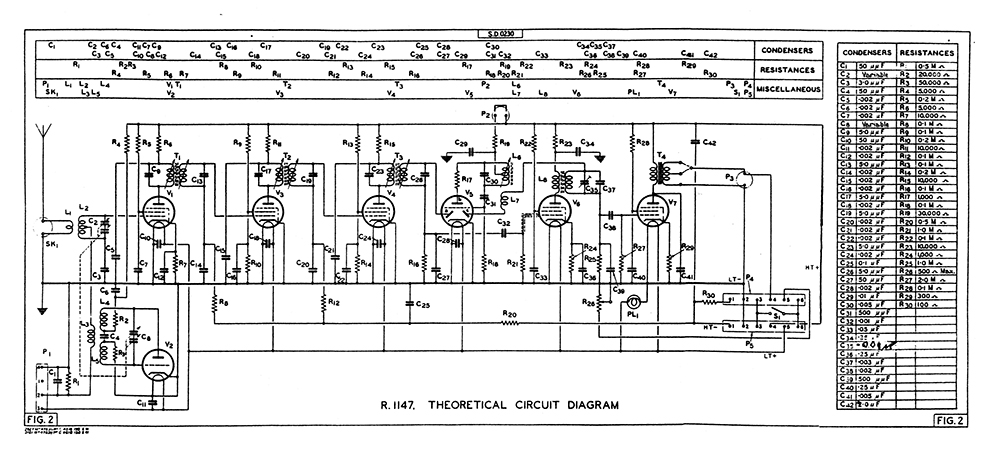
Here's the circuit diagram
for the R1147.. click it to see
a larger picture |
 |
|
Below you can see pictures
looking inside the box. There are a couple of pentode valves
(VR56) and a double diode triode (VR55) visible.
VHF tuning which appears to
cater for RF amplifier and oscillator is on the right.
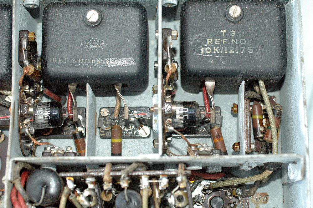
Another view shows the IF transformers
which were set to 25Mc/s and had a broad tuning to compensate
for oscillator frequency drift. Preset tuning controls for the
IF transformers are located in a line along the top of the picture
below. |
 |
|
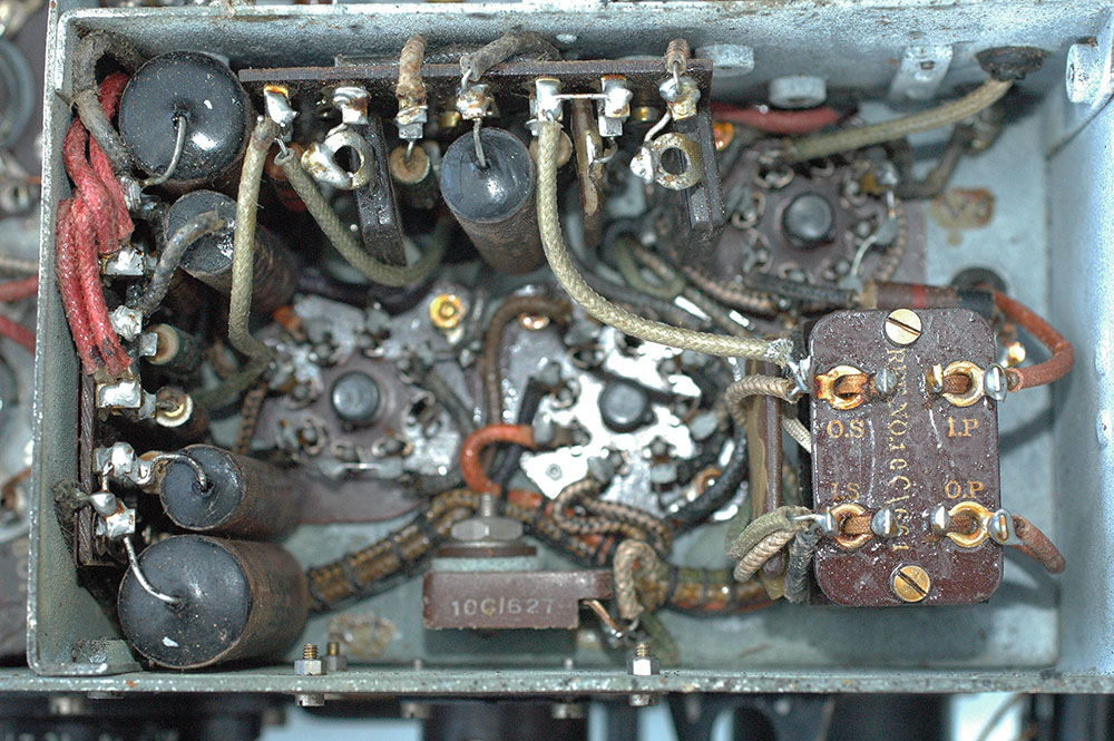
Below you can see the
other side of the chassis where you can see its unusual complement
of valves.
Bottom left is a triode (VR59)
oscillator, in fact an HA2 which is the version of the US 955
acorn triode made in the UK. Above the 955 is a VR95 pentode.
This is a ZA2, the British version of the US 954 acorn pentode.
The first IF transformer (10K12173) is top right. Next are two
IF amplifiers using two more VR95s with their IF transformers
(10K12175)
More detailed pictures follow
below. |
 |
|
Close-up picture of the 955 and 954
oscillator and mixer with their unusual valve holders. Presumably
the two differing materials were chosen to optimise the RF performance
but keeping wartime economy in mind. the first IF stage has a
Tungsram version of the 954. |
 |
|
The later version of this
receiver, the R1147B was redesigned to incorporate some EF50
valves. |
 |
 |
 |
|
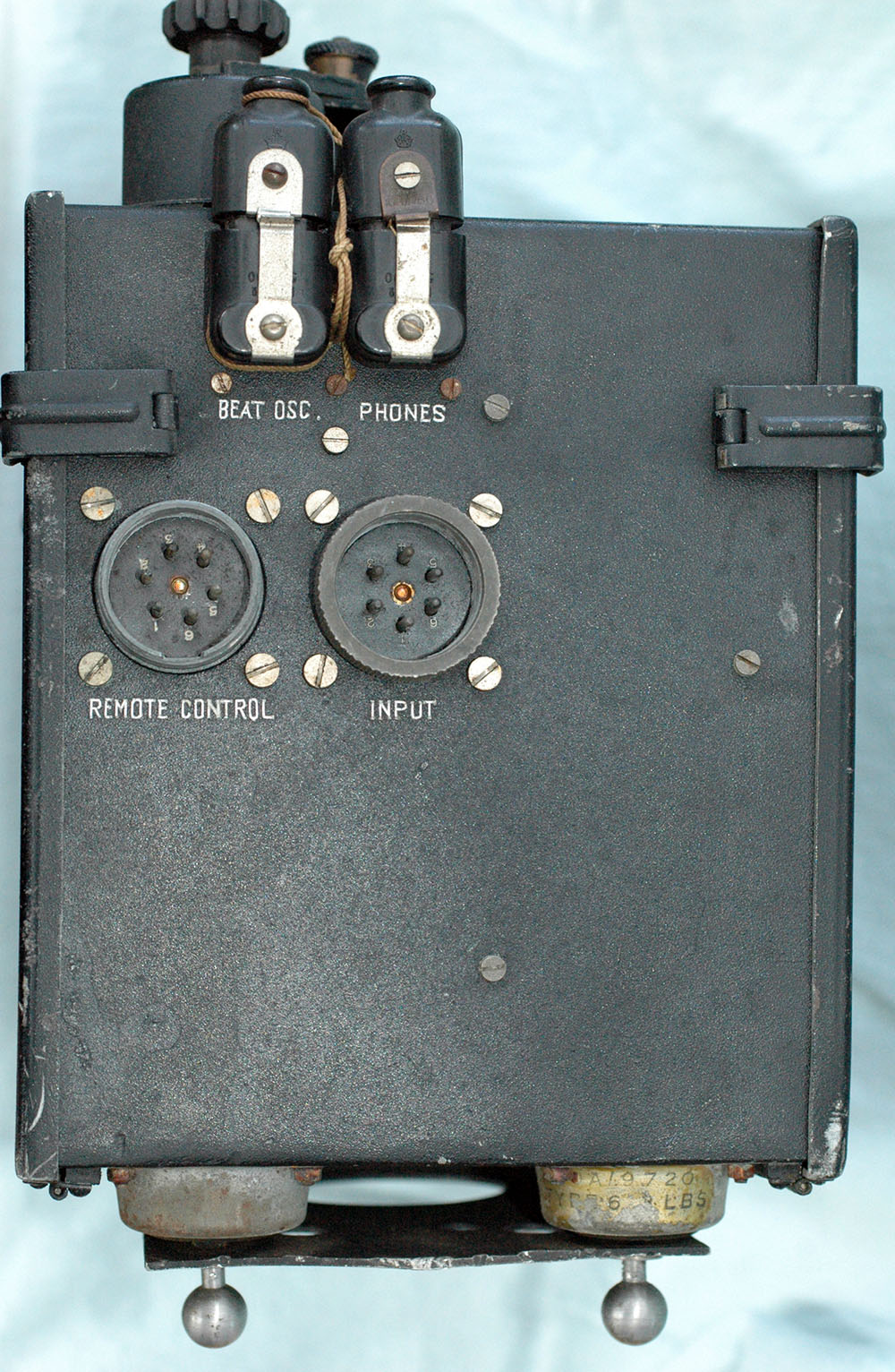
Below you can see
the side view of the receiver including its shockmount. The input
connector provides HT and LT from the power supply box.
The Remote control socket provides
audio output plus volume control connections and on/off control.
The picture below shows the
headphone output socket plus a socket labelled "BEAT OSC"
which carries a link supplying HT to the BFO (the triode section
of the EBC33). The knob shown behind these sockets allows the
BFO to be adjusted. |
 |
|
View showing the connection
for the remote control cable. The operator would use letters
A, B, H etc to select the appropriate beacon signal.
The blanked off connector (designated
"P1") was possibly used for testing the set in a workshop?
It connects to the LT+ and LT- circuits and the internal VHF
oscillator output coupling coil. |
 |
Remote
tuning control
|
|
This was designed for connection
to the R1147 plus a second remote control if required. Depending
on exactly where the set was mounted, the pilot could operate
the set directly or by remote control or, via an extension to
a further remote controller, the R1147 could be operated by a
navigator/observer.
To facilitate remote operation
a remote control box was fitted for the pilot or for the observer,
or both. These were slightly different in design, that for the
observer had a 6-way input connector wired to an on/off switch
and a volume control plus a 6-way output connector which was
coupled to the pilot's remote controller. The latter had only
a single 6-way connector and had an additional feature which
could switch operation between the pilot and observer. |
 |