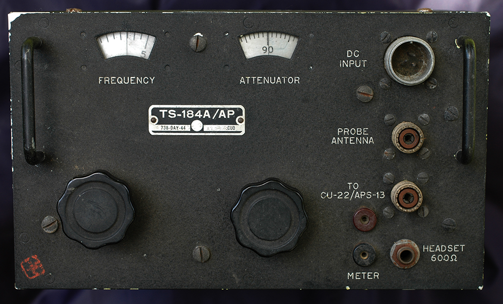
TS184A/AP Test Set
|
 |
|
This equipment, which
is basically a wavemeter, dates from 1944 and is typically American,
looking much like the RA1B and and ARR3 receivers, made from aluminium with
the front panel and case finished in black crackle paint. Although
I bought it as an IFF test equipment, I've since discovered it
was used for testing an early radar operating around 70cm. This
radar, the CU22/APS-13 (inscribed on the front panel) was fitted
in the tail of US aircraft to detect any enemy aircraft closing
on them from behind. In the late stages of WW2 when allied aircraft
were pushing well into Germany they needed protection from fighters
and this type of radar, together with a similar British version
helped to warn pilots of imminent attack from the rear. |
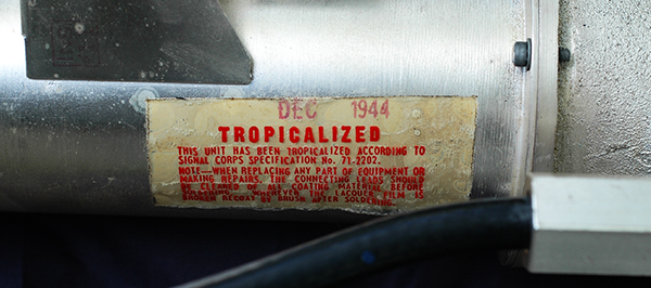 |
Here's further evidence for the
date of manufacture.
The label on the front panel, above,
includes reference to the contract under which the test set was
manufactured.. "738-DAY-44". |
|
 |
|
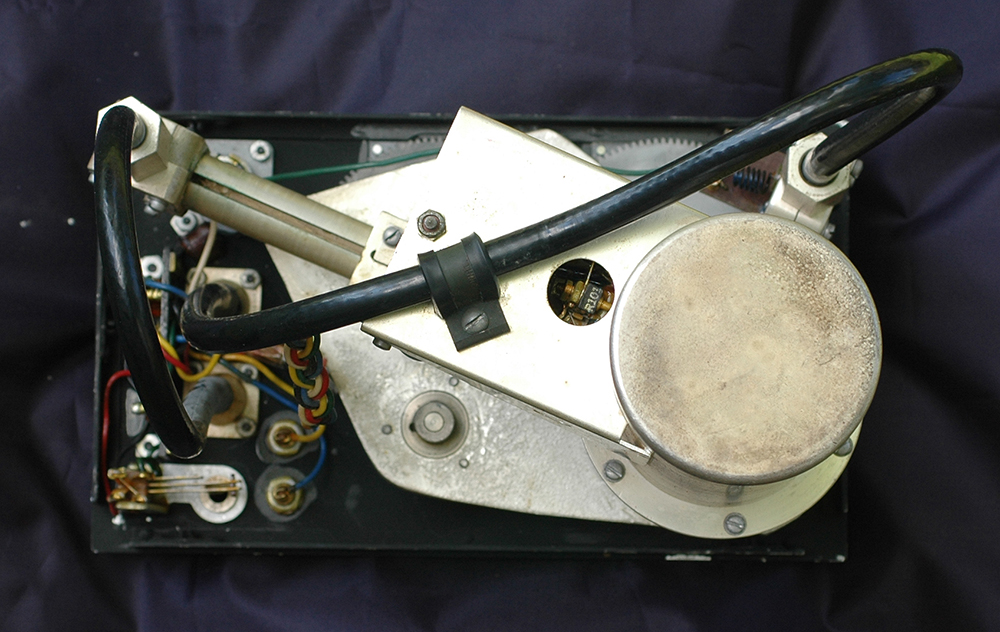
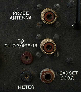
Above, you can see the
connections to the equipment. The thick black connections are
made from RG-8 coax and the woven cable carries power to the
70cm oscillator. Below is a view from the rear of the equipment. |
 |
 |
|
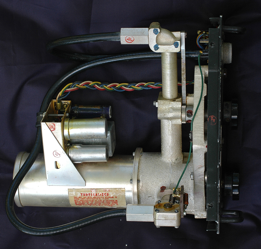
The equipment is very
simple in design, comprising an tunable cavity incorporating
a mechanical attenuator both operated by front panel knobs. Fitted
to the side of the cavity is a local oscillator using a 6J6 double
triode valve whose frequency can be varied by adjustment of the
tuning knob. |
 |
|
What does this test set
actually do? I'm only guessing, but given a radar equipment in
the factory, or in a workshop, you'd need a dummy signal that
emulates a reflection from an aircraft closing in on the transmitting
aerial in order to confirm the radar is working. The easiest
method of detecting a following aircraft is to transmit a signal
and listen for a return echo. By 1944, doppler effects were well
understood so by comparing the transmitted signal with its reflection
one could see any change in its frequency. See
a WW2 radio altimeter and a rather complicated J-Band speedometer
from the cold war. |
 |
I initially guessed this but it
turned out to be wrong (see the test results further on..)....
The signal from a working radar is picked up by a small RF probe.
This signal is fed into the cavity at its base and the local
oscillator carefully tuned until a beat note is heard in the
headset plugged into the lowest socket. My guess is the CU22/APS-13
is looking for a return RF signal close enough to its transmitted
signal to produce a beat note, so the local oscillator output
is fed to it via an adjustable attenuator to accurately mimic
a reflected RF signal.
By altering the local oscillator frequency
an emulation of an RF reflection can be made. The meter terminals
must be used to accurately monitor the difference between the
radar output and the local oscillator once a beat has been heard
in the headset. This will enable the radar to be proved to operate
correctly.
Of course, once any radar system had
been deployed the enemy would devise a method of jamming. Whether
the APS-13 had provision for anti-jamming I don't know...
Years ago Plessey sold a radar jamming
system to Syria.. but that's another story.. |
|
|
What's surprising is the
test set is still in one piece because most WW2 stuff having
applications far removed from day to day radio amateur use were
stripped down for parts. But maybe it was used? In fact, given
a suitable calibration chart, it would make a useful wavemeter
for the 70cm amateur band providing of course the cavity is tunable
to around 432MHz?
I decided to test the test-set.
As I had no schematic I needed to work out the connections. The
three pins at the power plug were tricky, but I soon discovered
the test-set uses only a 28 volt power supply. The 6J6 heater
is fed through the wirewound resistor adjacent to the valve.
A black wire is chassis so goes to 24 volt negative. The white
wire carries the 28 volt supply.. but what's the green wire for?
It connects to the end of the cavity and seems to end in a couple
of resistors and a decoupling condenser. I applied a voltage
from my variable PSU and increased it to 28 volts and the current
read something around 450mA. The 6J6 heater draws about 432mA
at 6.3 volts. Connecting a spectrum anayser to the output socket
revealed that there was no signal present so the 6J6 is not an
oscillator. I then connected the tracking generator to the Probe
input and looked at the results. I saw a really well defined
spike around 430MHz.
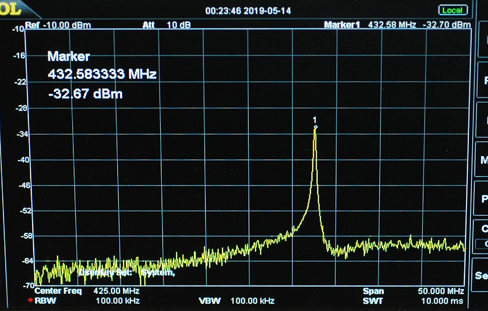
Below are some pictures of the
results. note that I carried out tests with the test-set out
of its outer case and this meant that the skirts to the responses
were dependent on the position of the input and output cables.
First the minimum frequency with the 0-30 dial set to the left
of 0 then the maximum frequency with the dial set to the right
of 30. |
 |
 |
|
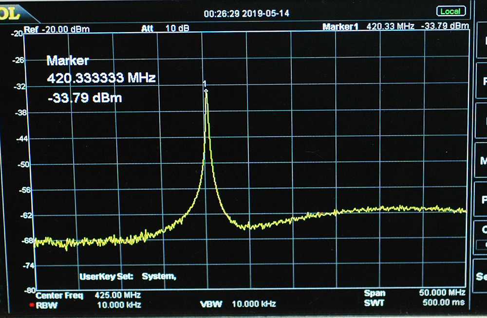
Then with the dial set
at precisely 20 (=420MHz) |
 |
|
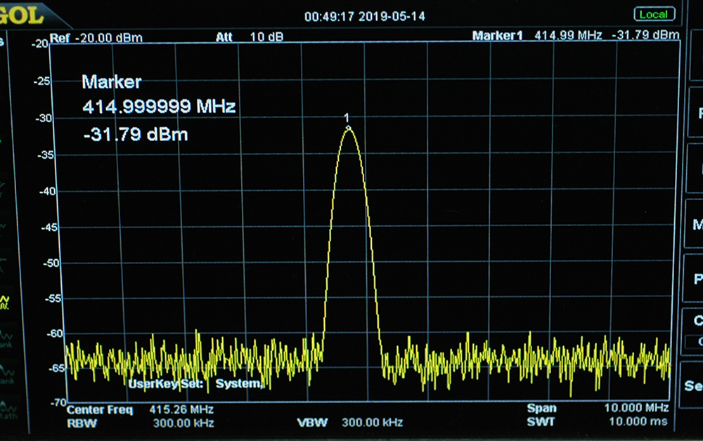
Now the results when feeding
the Probe input from a signal generator set to precisely 415MHz.
The RF input is set to 1000mV (=+13dBm). Note that the responses
were not affected so much by lead positions as was the situation
above. |
 |
|
Now the RF input is reduced
to 100mV (=-7dBm) |
 |
|
The final tests were to
check the effect of the attenuator and also to see what could
be heard in headphones. The attenuator works very smoothly and
precisely, producing a significant reduction in output signal
strength. At a setting of 50 (the dial shows 0-100) the signal
dropped to a level difficult to measure. What about headphone
output? With the signal generator set to 100% AM I could just
hear a tone but as modern headphones are very low resistance,
I suspect that the output would have been at a comfortable level. |
|
The conclusion I'm drawn
to is that if the radar uses Doppler principles the calculations
on the return echoes are carried out in the radar set and not
emulated in the test-set. Clearly there must be some modulation,
but whether that is pulse (at an audio frequency) or AM I don't
know. Maybe someone familar with the APS13 radar can advise me? |
|
Finally...can the equipment
be used in the 70cm amateur band? Not so much in the UK
where the band is 430-440MHz, but in the US where the band is
420-450MHz it's more useful. I guess the top of the cylinder
could be removed and a tight fitting plug fitted to raise the
frequency response somewhat. |
|
|