|
Goblin "Timespot"
Radio, S/No 107837
(Manufactured by British Vacuum
Cleaner & Eng Co Ltd, Leatherhead, Surrey)
Repair AC004.. April 2023
|
|
I last repaired one of
these in September 2003 and found it had pretty well classic
faults. The clock field winding was open circuit and many capacitors
were leaky and needed changing for modern types. Dial lamps had
failedand the IF transformers needed aligning as well as the
long, medium and shortwave coils. |
 |
|
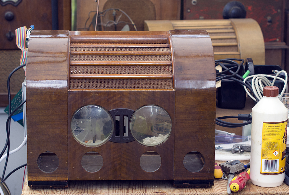
As you can see the clock plastic cover is damaged
but the owner says he'll replace this later. The chassis is remarkably
clean but that transformer and electrolytic fastened to the speaker
mounting board look out of place. Also out of place is the 6V6GT
which I soon discovered should be fitted in the socket next to
the end and not in that end socket. The 5Z4G rectifier wasn't
in the free socket but just loose inside the case. I plugged
it into the free socket next to the end as shown below. Because
the 6V6GT was firmly plugged into place could this have been
why the radio hadn't worked? Hopefully the valves different pinning
arrangements (see below) should have prevented damage. |
|
|
 |
|
|
 |
This is the S25 model and, as you can see on
the label, it was made by a vacuum cleaner company which is a
little odd. That business started in 1903 and I guess the owners
were trading on their good name rather than devise something
new and unkown.
The same company later also made the Teasmaid which
brewed a pot of tea in the morning just before you awoke. We
had one of these back in the late 60s and early 70s which was
wired up to our FM radio (an ARR3) |
|
 |
|
The set is a bog standard superhet but is quite
interesting as it uses a set of six commercial Wearite coils
for long, medium and short waves and, because of the absence
of tuning cores, tracking makes use of padder trimmer capacitors.
Oddly the wavechange switch is marked Medium-Short-Long and is
not as depicted in the schematic above.
Alignment follows standard practice ... trimmer at
HF end and padder (rather than tuning core) at LF end with lots
of repeats to match tuning to the dial. The tuning mechanism
has normal, slow and fast which are automatically selected. The
IF is 465KHz and turned out to be not too bad but waveband alignment
is hopeless, partly because the pointer was quarter of an inch
adrift, but not entirely so. |
|
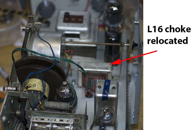
The choke (L16) and an extra 8uF smoothing capacitor
were screwed to the loudspeaker baffle board (see
the rear view above) and with the capacitor ground sharing
louspeaker ground. I didn't like this idea because it would be
a source of hum, and makes chassis removal tricky, so I removed
these and fitted them to the chassis instead. The reason for
fitting L16 was that the original design used a mains energised
loudspeaker which embodied a field coil instead of a magnet.
My guess is that this speaker was damaged some time ago and was
replaced with an ordinary permanent magnet moving coil type hence
a separate choke was required. |
|
|
|
The receiver has obviously been looked at previously
as there's a replacement capacitor at the 6V6 cathode, however
C7 responsible for driving the audio output valve looked very
distressed so I fitted a new 47nF in its place. AGC is extremly
good with over 30 volts available on strong signals. The tone
control is very basic but quite effective. I also replaced a
second very sticky 0.05uF at C9 with a 68nF capacitor.
Although the owner suggested the clock was u/s the
second hand went round once mains power was applied. The clock
is connected to the mains supply before the on/off switch so
runs whenever the mains plug is powered. Note that in keeping
with all clocks of this design it can start backwards. Merely
switch off the mains supply at the 13-amp socket and switch on
again and the clock should go forwards.
Switching on the receiver at first resulted in loud
crackling which disappeared after a few minutes and I also noticed
the long wave dial markings were extremely faded. The case has
been treated perhaps with linseed oil? but I noticed that it's
somewhat out of kilter and the veneer at one side has lifted
over a large area. Whether the set has been bumped in shipping
or it's been glued together in the past without checking alignment
of the wooden parts. I'll need to investigate. |
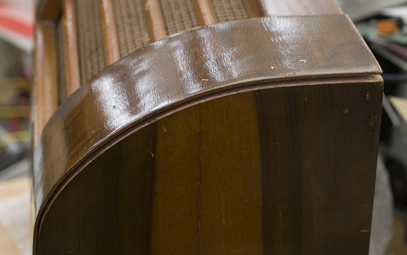 |
Looking at the case of the radio revealed some
problems. My own Goblin radio was suffering from lifting veneer
that stubbornly refused to reliably glue in place. You can see
opposite loose veneer but looking below you can see why it's
happened. |
|
 |
Whenever a wooden radio is put in the hands
of someone tasked with moving it from A to B, even though it
might be marked "fragile" or whatever, there's no guarantee
it will arrive safely.
Years ago I had to ship a wooden radio from Bournemouth
to California. It arrived smashed to pieces.
The evidence here is that the radio was dropped say
4 feet or so upside-down. The weight of the chassis caused the
wooden base to which it's screwed to crack the glue holding the
case together. When it was made they used small pins to hold
it until the glue dried and these were now detached.
Both sides of the case had shifted a quarter of an
inch as you can see here.causing the veneer seen above to part
company with the side. The new position of the sides was pretty
solid because the securing pins had half pulled out and jammed
the wooden pieces in their new positions and there was no way,
because of the gaps, that the veneer would glue back in place. |
|
 |
|
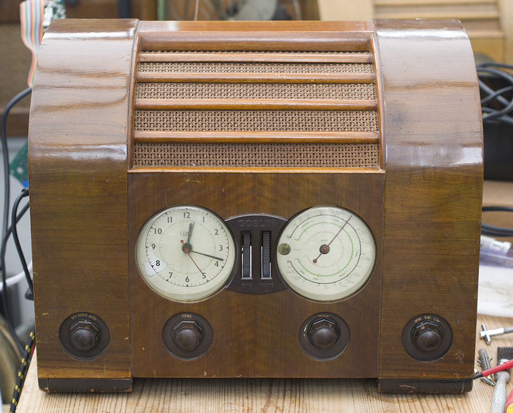
Here's the case restored. The method was to
apply lots of force to reverse the cause of the problem. I used
a large furniture cramp and packing to prrevent damage to the
wood. The pressure (top to bottom) pushed back the pins and the
worst side pressed back into place with lots of cracking noises.
I then used a couple of screws to hold the side in position.
A similar pressure on the other side and some pressure front
to back completed the job. Then I used more screws and PVA glue
to secure the wood and the veneer. You can see the gap shown
in the pevious picture have closed up. In the background, purely
accidentally, you can see my own Goblin
radio bought 25 years ago and
notes for a repair I carried out in 2003.
The radio chassis now works well after swapping a
few critical parts. I'm pretty sure someone had screwed the trimmers
at the coil pack as most were miles from the correct settings.
These are extremely critical and the slightest adjustment can
make the receiver a deaf as a post. The alignment process in
this model of radio is not particularly good due to its design
but the aim is to average out the receivers performance across
on each of its three wavebands.
To get the best from the radio will need a decent
longish wire to pull in stations such that they are stronger
than local domestic electrical noise.
Pictured below only awaiting rear covers |
 |
 |
|
|
|
|
|
|
|
|