Radio Interference.. October 2013

 Every time I listen on the short wave bands I'm more upset about the level of man made interference. Yesterday I switched on my recently overhauled Racal RA17 and tuned to the 80 metre amateur band. It took some time to work out suitable settings for the gain controls before I could hear any amateur transmissions.

First, I had to switch off my new surveillance camera. I'd already noticed that this completely messed up long wave reception on the Roberts portable in the bathroom some 80 feet away. In order to listen to Radio 4 this set has to be carefully orientated to eliminate a huge interfering signal. I now know that this interference covers most of the shortwave band. a second camera which has recently replaced the first one is just as bad. Some time I'll try to work out exactly where the interference is being generated. Most electronic items in the house generate interference which is mainly a sizzling sound but our new washing machine sends out RF signals carrying musical notes. I plan to make recordings.

Fluorescent lights used to be the main short wave noise generators, but now I understand that LED lamps might be the worst offenders. This is slightly odd, but in fact it's not the LEDs themselves that are to blame, but their power supplies.

As an aside….it's interesting to recall that the UK mains voltage didn't just get decided overnight. It took years and years and years. For ages the UK was criss-crossed with mains cables carrying voltages ranging from less than 100 to over 400 volts and could be AC or DC, depending on what had happened in Victorian times.

In large towns and cities the mains voltage had been logically determined by the most common requirement. In those early days before wireless and decades before television it was street lighting and the illumination of large buildings that mattered most.

With the advent of carbon filament lamps which often replaced carbon arc lamps the most efficient operating voltage was around 100. Later, with the emergence of tungsten filament lamps this increased to over 200 volts.

To support easy transmission and distribution AC was a must, so 240 volts AC became the new standard. In cities and large towns it used to be economic to provide DC and it took ages for this standard to finally disappear.
Eventually the UK standard voltage was chosen countrywide as 240 volts AC.

Turning back to radio interference.

What is it about these new fangled low energy lamps and in particular LEDs that can wipe out entire amateur bands?
It hinges on the best operating voltage.
Unfortunately an LED works at circa 2 volts DC.
There are therefore two problems.
Firstly we need DC, secondly we need to develop a voltage miles less than 240.
True, we can string LEDs together in series and this helps enormously as their operating voltage can be increased accordingly, but nevertheless we still need a DC power supply from which we can run the lamps.

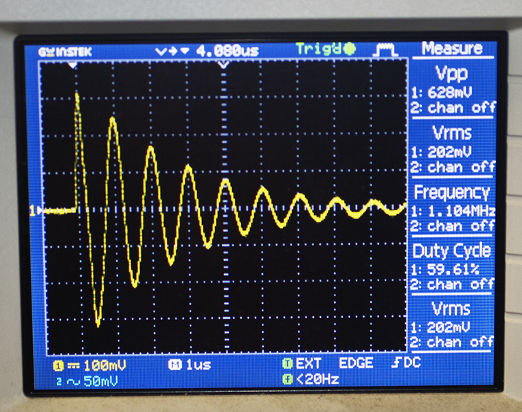
For various reasons, "clean" power supplies using a transformer and rectifier are nowadays seldom seen, having been superseded by switch mode types. These usually operate in the tens of kilohertz and for best efficiency employ steep-sided pulses rich in harmonics stretching way up to the VHF radio spectrum.

We now come to a point which is usually overlooked or glossed over by engineers.
In the last decade or so the whole of Europe has introduced harmonization of mains voltage. Very little has been done to the generating plant and distribution infrastructure so in the UK the mains voltage remains at 240volts AC. Similarly, on the European continent their mains voltage generally remains at 220 volts AC.
Harmonization merely meant that the maximum and minimum mains voltage over the whole of Europe was specified to be within certain limits. The numerical values of these limits were the only thing that changed.

Because of this fiddle, the correct operation of every piece of electrical equipment that existed before harmonization was put at risk and to that must be added every piece of equipment manufactured to drawings produced before the implications of harmonization took hold.

The result of the change in mains specification means that plugging in a continental designed and manufactured equipment into UK mains resulted in a possible serious reduction in its reliability and at worst, within a relatively short time, destruction of some of its parts.

Looking now at LED lamps designed for mains operation.
If these are designed for use over the whole of Europe then their power supplies must accommodate a rather large variation, ranging from the continental 220v minimum value to the maximum UK 240v value.

Studies have shown recently that LED lamps generate huge amounts of radio interference when continental manufactured units are operated from UK mains. The reason might be simple. Harmonization of mains means that power supplies need to run at voltages in the UK that are much higher than those in most of the factories where testing is carried out.
A lamp might easily pass interference tests in Germany but would fail dismally in the UK where the mains voltage is a lot higher.

Can anything be done to rectify the problem?
Can one complain to anyone?
The practical answer is no, at least one can complain, but it is highly likely that nothing will be done.

I suppose one could choose a lamp that produces less interference, or even use a mains conditioner to reduce the operating voltage to a level which minimizes interference?
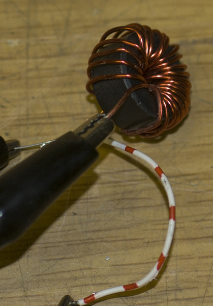
Filtering is unlikely to provide much improvement if the interference is radiated. Certainly this can be shown to be the case from experiments with my Roberts battery operated radio. Simply, the fact that re-orientating its ferrite rod can eliminate the noise proves it's radiated and suggests the answer to minimising interference may lie in one's choice of aerial.

An interesting side issue comes to mind. Now that we have to rely on digital TV and also now that digital radio is becoming popular, what about the effects of interference to those transmissions?
Maybe the answer is to switch off all the lights and listen in the dark, or use candles and oil lamps like many of the first BBC audience. That is unless you still have the odd tungsten lamp, or like me use 240v halogen lamps?


 After listening to the medium waveband on my recently refurbished R206 and hearing all sorts of noises clearly emanating from local sources I thought again about erecting an aerial that was proof against at least some of the noise. The main problem is that to make the aerial perform best it should be tuned to the desired frequency of interest and pointing towards the origin of the transmission. My first thought was to fit the tuning condenser in the workshop, but the only way of connecting this to the coil mounted on a mast would seem to be coax (to avoid pickup of noise) which would provide a screened path. I set up a simple experiment and soon discovered that although this would work in practice the capacity of the coax cable acts to tune the coil. Several metres of cheap TV coax tuned a Wearite PA1 to 175Kc/s. because when I measured its capacitance it was 425pF. Adding an extra 170pF across the open end of the coable tuned the PA1 to 150Kc/s. So, the method does work, but the cable capacitance makes the tuned circuit a bit top heavy with capacity. Ideally the more wire in the pickup coil the more signal so this method defeats the object.

Another method would be to use a varactor diode to tune the coil using voltage from a pot. The best varactor diode I've seen is 80pF rising to 110pF which is miles away from say a 350pF variable condenser, but as medium wave tuners are not very popular with manufacturers these days I might be able to find a suitable type if I keep looking....

Thinking about other methods... a motor driven variable condenser or a set of relays able to switch in a set of fixed condensers, or maybe an electronic switch to do the same job? Even a servo driven arrangement?

Then I'd need to consider a method of rotating the loop aerial, or ferrite rod aerial. In fact, with some ingenuity a ferrite rod which could be moved through the coil to tune it? Maybe a wideband amplifier using a FET mounted up the mast is a possible solution? Back to the drawing board... but, after checking for a suitable varactor diode, this time on a favourite auction site I turned up a pack of four diodes type BB510 for a fairly lowly sum (click to read the spec). This varactor seems ideal for tuning a loop aerial across either long or medium waves. Adding a high gain amplifier at the top of the mast could have a major advantage because interfering signal pickup on the feed system would be much less than the amplified output.

Thinking about a suitable amplifier, I recalled designing one for a car radio many years ago and quite recently I tested it to see if it could be used as a wideband VLF amplifier (click to see test results)... A second design, also based on a 2N5109 might be worth building (see below). For BB551 read BB510.


 I constructed the amplifier on a piece of metal cut from a tin can with a view to fitting this into a small diecast box. Initial experiments were confusing because I could get only a limited tuning range. This was resolved when I decided to go back to first principles and work out the theory. My method is to construct a simple spreadsheet which is driven by key parameters such as capacity and inductance. I found that if you made the minimum capacity for the varactor diode too large it would significantly reduce the tuning range, just as I had found. The solution wasn't to replace the varactor, but to change the base coupling capacitor. This was marked "500" which I'd assumed was 50pF but which my capacity tester revealed was over 600pF. Different manufacturers practices, not to mention passage of time has resulted in too many ways of marking capacitors.

For 500pF for example you will come across the following markings: 0.0005uF, 0.0005mF, 500uuF, 500mmF, 500, 501, 0n5, n5. 500pF (and no doubt there are more...)

With a proper 50pF coupling capacitor the tuning range was corrected and tuning was much more pronounced on weak signals.

Dispensing with the standard tuning coil and substituting a frame aerial coil showed lots of promise. Medium wave signals were now very strong and much better than from my long wire aerial. The main difference between the two of course being the extra gain from the amplifier and a remarkable decrease in interference (the main object of the exercise).

Interestingly I can now hear interfering signals in a different way. Instead of an overpowering racket of noise uniformly spread over the entire band, the main sources of interference are a sort of wailing sound repeated across the medium waveband at regular intervals. Each occurrence is tunable and each has a bandwidth which is wider than the average broadcast signal.


 The picture above shows the prototype amplifier with the test coil removed and a choc block for the frame aerial. Note that the varactor is a BB510 not BB551 shown in the schematic above. Two 47 Kohm resistors in parallel are for the auto-bias, not 22kohm as shown above. The 12 volt zener diode is fitted to prevent damage to the varactor if the supply voltage is increased. The 100kohm pot is fitted to an old computer power supply case and the choc bloc connects the frame aerial.


 The initial frame aerial can be seen on the bench. This had been reduced to only 7 turns of wire because of the coupling capacitor error. The later frame aerial is larger and has eleven turns of wire on a square of 0.6m resulting in an inductance of 308uH. This tunes over the top part of the medium waveband. The amplifier is plugged into the R206 undergoing restoration.

Referring to my spreadsheet the tuning range of the larger frame aerial should be something like 380KHz to 1000KHz, assuming a shunt of 50pF due to the coupling capacitor and transistor. Reducing the coupling capacitor to say 20pF should give me a range of 380KHz to 1433KHz and removing a turn from the frame will give me 400KHz to 1500KHz.

A long wave frame can also be constructed. From rough calculations this will have 70 turns of wire and will tune 150KHz to 562KHz.

If I wanted to add a long wave range which just overlapped the medium wave frame coverage, I'll need 4mH which works out at 140 turns resulting in a range of about 100KHz to 400KHz. The next range down to VLF would be 62mH requiring 2200 turns covering 27KHz to 100KHz.

I was finally happy with the frame aerial. It now measures about 115uH (this figure varies with its proximity to metalwork in the workshop) and tunes 550KHz to 1.6MHz, so just covers the medium waveband. I changed the collector resistor from 220 ohms to 1.2Kohm and this reduced the supply current from 5mA to 2mA without changing the performance. I also lowered the base capacitor to 20pF to improve the tuning range of the amplifier.

Going back to my original spreadsheet; this gives me a minimum capacitance of 85pF and a maximum capacitance of 685pF. I guess this means that the coil has an intrinsic self-capacitance of the order of 55 or 60pF.

Next I'll try adding a second coil to cover long waves and select it via a small 12 volt relay. To improve long wave pickup I'll extend the frame and this will reduce any mutual coupling between the two coils. I added an extra 300mm to each leg and wound lots of turns. When I'd exhausted the roll of wire the inductance of the long wave coil was a little under 1.5mH.

According to my speadsheet, if I switch in an extra varicap diode making two in total I should be able to tune from 379KHz to 117KHz.

During my experiments I came across a really simple method of improving, or at least understanding, the performance of a loop aerial.

If you connect the loop to a square wave generator having an output around 1KHz or less the coil will ring at its resonant frequency. Given the inductance value of the coil you can them work out its self capacitance. The smaller the self capacitance of the loop the better it will work. To make the measurement you need to reduce loading effects so feed the loop via a 10Mohm resistor and use the 10:1 setting of the scope probe. My scope has a calibration connection on the front of 2 volts p/p so I used this instead of a separate square wave generator. The amplitude of the square wave should be ideally say 5 volts to 10 volts peak to peak and I found this higher voltage was necessary if the self capacity of the coil or the coil inductance is low. Also, it was beneficial if this was the case that the feed resistor be reduced to say 1Mohm. Below are examples of the ringing test using four random coils. The two test circuits are shown. I used the second circuit for the tests because the square wave voltage wasn't suffient for any of the four coils.

Some of the result are puzzling...


 Inductance 1.324mH res 3.3ohms

Self capacity 24.4pF


 Inductance 569.4uH

Self capacity 36.5pF


Inductance 2.5uH 

Self capacity 356pF ??

Both this coil and the next one needed a bit more square wave input than the larger ones. The top picture shows the results from too low a voltage whilst the bottom one is better. I also reduced the feed resistor to 1Mohm for the second test.


 Inductance 36.8uH res 1.1 ohm

Self capacity 259pF ??


 See further experiments...


 Above is the experimental aerial in its final position fastened to a 5" x 1" plank supported by a small leylandii tree. In the front, about 8 feet away, supported by a table with the umbrella removed is my VHF aerial. In the background is a neighbour's mains cable. The worst remaining interference, which is now fairly low, comes from my network cabling over which runs signals from a pair of surveillance cameras.

  I'd put the experimental aerial aside as a pending exercise but quite recently, May 2016 we had a power cut. Sometimes the power is restored quickly but in this instance it remained off for a few hours. I'd bought a UPS (uninterrupted power supply) for our computer and connected it up to the monitor and computer box so we were able to just close down the thing successfully. The last time this happened (and the reason for buying the UPS unit) resulted in my hard drives being badly corrupted.

After some ten minutes I realised I could check the radio spectrum and compare reception of medium and long wave stations with usual conditions. My Roberts portable indicated that all was not well. In fact reception conditions were just as bad as those when mains was present. Why was this? The answer was simple. The UPS unit was responsible but is it the worst offender when mains are present. I can report that it isn't. It only generates huge interfering signals when there's a power cut. The operation of a typical UPS relies on a set of lead acid batteries running a DC to AC converter, and of course this includes a very powerful chopper power supply running at tens of kilohertz with harmonics reaching up to VHF as per usual. I suppose I could look at the spec for the UPS and see if it specifies an interference level, but I imagine this would be a waste of time. If I need to protect my computer and listen to medium and long waves, I'll need to build a new aerial such as the one with which I've been experimenting.
 

 Wireless Keyboard and Mouse- RFI Problems

 Over quite a long time I've been having a problem with my wireless keyboard which occasionally refuses to work. It will usually sort itself out if I remove the battery or turn it upside down and bash it, but not always but generally recovers if I wait until the next time it goes wrong which might be hours or even weeks. It's a Logitech MK700/MK710. That kit came with a wireless mouse a Logitech M705. The operation of the mouse is infuriating. It will suddenly drop something being dragged or fail to click a shortcut. If I bang it really hard or mess with the batteries it will often start working again. It was so bad the other day I opened it up and checked the interior for dust and fluff. Sure enough there was plenty of fluff and I extracted this with tweezers. I bent the battery springs a little and reassembled it after looking for bad solder joints.. there were none. The mouse worked for a few minutes then acted up so I looked for a replacement. The M705 was too expensive so I purchased a new 6-button mouse made by Canyon, their model CNS-CMSW4B which was very cheap. I plugged in its dongle and tried it out. It worked fine except that it dies after being unused and needs a button press to make it come alive. At first it worked as expected but then it started turning itself off and got very lumpy in operation. In fact it behaved in much the same way as the Logitech M705. Changing the USB drivers failed to fix it so I wondered what was happening.

 I read the information on the new mouse and noticed it operated in the 2.4GHz radio band. That band is also used by routers for setting up wi-fi and another device which has been plaguing me for ages, our Siemens Gigaset house phones. Our phones were three of the model A400. These operate wirelessly and if I use one I get a headache. The spec tells me I can switch them to low emission, but I can't. I suspect our A400 are an early example without the ECO facility so operate on full power continuously.

I purchased a set of new phones. These are the C430A which, unlike the A400, have an answerphone which we decided we'd like. I installed these but as yet haven't looked at their ECO setting. I looked at my new mouse.. it was failing to click on anything although the laser was on. The mouse mat is adjacent to the C430A phone. The penny dropped. The mouse was latching onto the phone signal instead of the signal from its dongle located 4 feet away. I removed the dongle and added a USB extension cable then refitted the dongle so it was now closer than the C430A phone. It worked! The problem, all along was interfering RF from the phone.
 

 Return to entrance