|
|

|
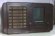
The valves are 6A8 frequency changer, 6K7 IF amplifier, 6Q7 detector/audio amplifier, 25A6 audio output and 35Z4 rectifier. The set used a line cord which has failed and I am modifying it to use a simple ballast resistor and diode arrangement. Although this is not going to be a repair for the purist, it will end up a lot safer with a modern mains lead and moulded 13amp plug. I have written some notes on this which will be published in the "Repair Tips" section when they're complete. The set has a live chassis so all tests are carried out using an isolation transformer otherwise nasty things would happen to my oscilloscope and signal generator. Some "breadboarding" is apparent in the picture where a chain of ceramic resistors can be seen. These air cooled types run so hot that the solder melts and they fall apart but the final ballast resistor will be a 50 watt metal clad device bolted to the chassis. I tested the valves and found they were all in excellent shape but a quick check under the chassis revealed an open circuit 10uF electrolytic at the cathode of the output valve and a 0.025uF audio coupling capacitor at the grid of the 6Q7 with a leak of around 3 megohm. Other components were deemed to be serviceable but I replaced the two bad components with new devices. The electrolytic is now a miniscule Japanese component and the 25nF capacitor a polycarbonate type. Incidentally an excellent source of capacitors is virtually any old TV chassis. Most use lots of high voltage types eminently suitable for old radios. Given three or four different makes of TV chassis virtually any value capacitor may be salvaged. These will range from disk types, high voltage pulse types and decoupling varieties used in mains input circuitry. Because radios have been repaired over the years with whatever components were around at the time I have no compunction against using the latest types. I found an interesting design fault on the chassis. The dial lamp was set to one side of the illuminating hole in the metal at the back of the scale. Thinking it had come loose and shifted, I repositioned it to line up properly and later wondered why the tuning capacitor jammed half-way closed. A grub screw holding a pulley was fouling the dial lamp. After setting the lamp back to its angle of 45 degrees I restored it to the way the factory had probably been told to do it back in 1939 when the fault had no doubt been corrected on the production line by modifications to their drawings! When powered up the audio was distorted. This was primarily due to a loose speaker cone. The glue at the back of the paper re-inforcing ring had failed and the cone was moving in an uncontrolled manner. One of the tuning capacitor vanes was bent and a loud crackle manifested itself at one third mesh. Straightening the vane sorted this out. I checked the remainder of the capacitors and resistors during the realignment because I found that although medium waves were tolerable there was some instability in the form of motor-boating at the low end of the band and besides long waves being pretty deaf the RF stage seemed to be oscillating. All the components tested OK except the odd leaky capacitor in places were leakyness didn't matter. I input 451 KHz which is the slightly odd IF and peaked up its four trimmers for maximum output. Now there was not only instability across the long wave band but the whole of the medium waveband was similarly affected. Not to be put off I continued with the realignment and the number of stations increased tenfold... but so did the instability. Something was decidely wrong! I tuned the 451KHz rejector in the aerial circuit then started to decouple various parts of the circuit looking for the point where the circuitry was misbehaving. Nothing helped and though signal strengths were now really good the complete medium and long wavebands were full of heterodyned signals. I checked the HT line and found that without the line cord that was a little high. Was this the answer? I inserted an additional 470 ohms in series with the speaker energising coil. Now the voltages were right but absolutely no change to the oscillating RF stage. I wrapped foil round the valves one at a time... no help. Back to first principles... just look at the circuit and think hard. I noticed that there was a moulded capacitor decoupling the audio stage to ground. I also noticed a second moulded capacitor decoupling the RF stage to ground. But wait... it wasn't ground, it was the metal case of the volume control. This looked like a Radiospares component and must have been fitted to replace the original many years ago. But unlike the original, the new control had a metal can that was electrically floating so that the two decoupling capacitors were effectively in series, connecting the audio stage to the RF stage... a feedback loop! I shorted the potentiometer case to ground; the oscillations ceased and Radio Solent appeared like magic. Presumably the set had never worked properly since its last repair, maybe 40 odd years ago! When I tested the receiver, with its new 50 watt ballast resistor bolted to the chassis adjacent to the output valve and the underside of the speaker, things got uncomfortably hot. The resistor has a design temperature of up to 250 degrees centigrade and needs to be better cooled than the small chassis can manage. As room inside the set is very limited I had to reposition the main HT smoothing capacitor and fit an aluminium finned heatsink in its original place. To this is bolted the ballast resistor. Not original maybe but not too disimilar to the model that followed this one. That's designers didn't have such a difficult job however as they used valves with 150mA heaters, not the 300mA types fitted in the early model. Dissipation is proportional to the square of the current hence I was dealing with four times their heat problem. I suppose I cheated a little as the silicon diode I fitted wasn't available to the old designers and this effectively reduced the problem by half. |
 click on meter