|
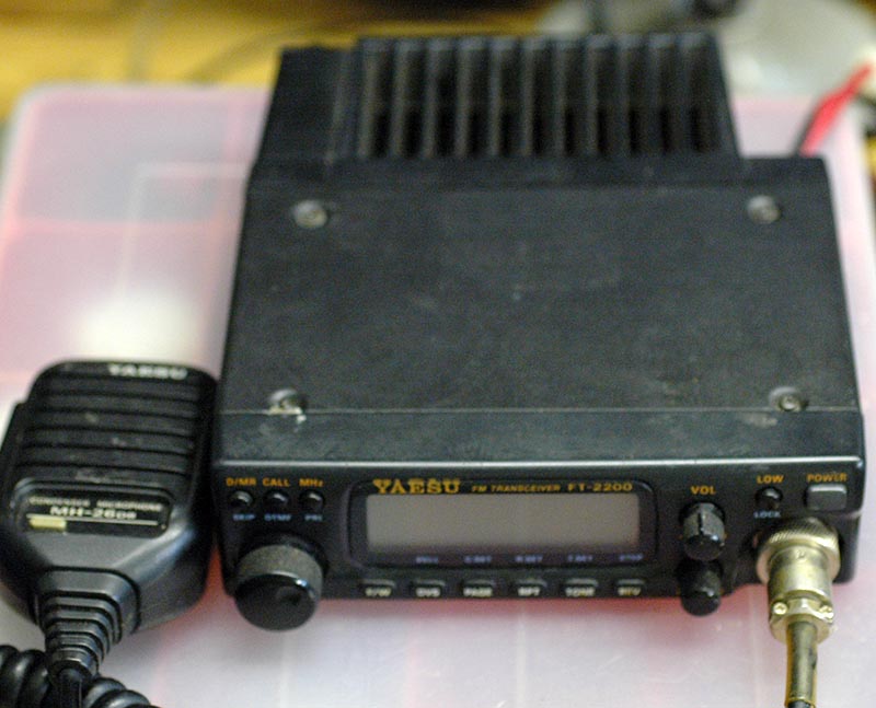
I powered it from a small bench power supply set to 12 volts and turned it on. It seemed to work, at least on receive and the display showed a frequency in the 2-metre band. The display appeared to be a liquid crystal type using one or more small tungsten filament lamps to illuminate it. I twiddled the frequency control knob and the display numerals dissappeared. I rocked the control knob slightly and the illumination went out. Time to investigate. The outer case comprises two bent pieces of steel each fastened by eight screws, some of which hold in place both parts of the outer case. A small Philips screwdriver is required as the screws are pretty tiny and once the two covers are removed the main circuit board is revealed. I looked at the soldering using a magnifier but all seemed well. Next I needed to detach the front panel to get to the display. Three of the largest knobs just pull off leaving the remainder of the various little buttons in place. Next the front panel. This is held in place solely by four holes formed in the top and bottom edges which engage with clips formed on the adjacent metalwork. At this point beware that some of the plastic push buttons are liable to fall out, including a spring behind the on/off switch button. Once the front panel is removed you can see the display module and the filament lamps. The next step is to remove the nut securing the display circuit board assembly to the thread around the tuning control shaft. In this example, once the nut was removed the assembly was loose and the cause of the problem was revealed. The assembly is designed to mate up with a circuit board at its rear via a tiny plug and socket and clearly this was the cause of the problem. I suspect the failure of the display was jointly due to the securing nut being slightly loose and slight tarnishing at the connector pins. To check that there was sufficient springiness in the socket I used a fine needle to jiggle the metal inserts then applied a small amount of switch cleaner. It did appear from solder residue around the filament bulb wire ends that these had been replaced in the past and its possible that the securing nut wasn't firmly tightened up. It's slightly awkward as the nut is fitted in a well in the plastic assembly. At this point check that the relevant push buttons are properly located then click the display assembly into place and fit and tighten the nut using bent-nosed pliers or a suitable socket. There should be a reassuring click from the plug and socket as it mates together and it shouldn't be loose. A quick test showed the display lit up then I refitted the front panel and top and bottom covers, again checking the various push buttons were working. The rig provides 5, 25 or 50 Watts output explaining the substantial rear heatsink. Besides the two-metre band you can also tune the Air Band which provides AM reception. If I have time I'll check the RF power output but the spec says I'll need at least 12 amps of power to do this, so it can't be especially efficient? Next I need to fix a much larger, HF transceiver owned by the same radio ham. |