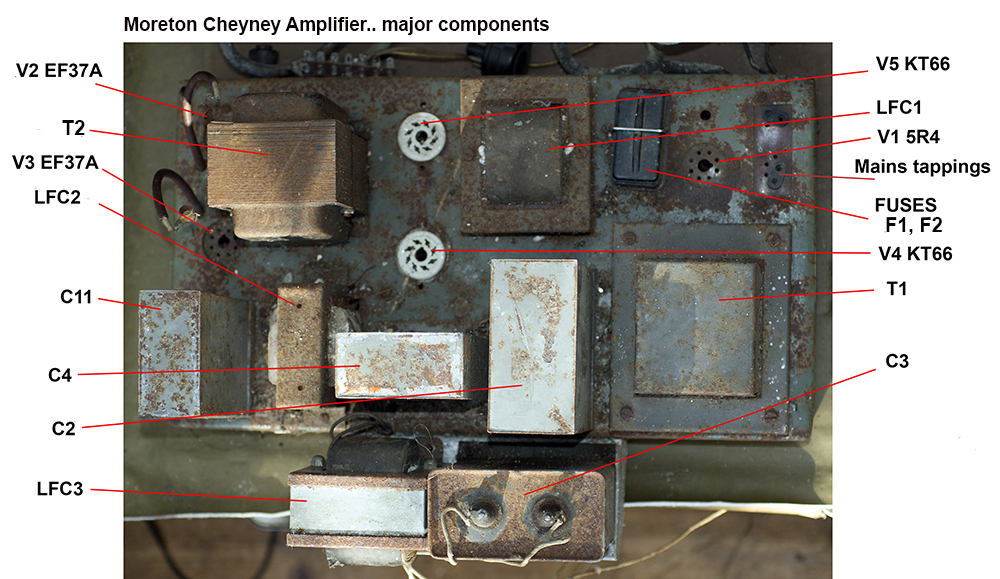
Rebuilding the Moreton Cheyney Amplifier
|
|
The amplifier as
you can see from original photographs was in a dire condition,
having been stored in wet conditions. Is it worthwhile to attempt
to tackle a rebuild? Well, this amplifier, which was designed
to accompany the Moreton Cheyney receiver,
is almost certainly, like the receiver itself, the only one in
existence.
Whilst the receiver has only
been slightly modified (or probably bodgingly repaired rather
than modified), the amplifier has quite certainly been modified
to a considerable extent. Rather than guess the original design,
I've decided to rebuild it in it's last working state. Fortunately
there are clues to help me to do this. For example, the amplifier
last used a pair of push-pull KT66 beam tetrode valves driven
by a pair of EF37A pentodes. The power supply takes up the lion's
share of the chassis.. in fact parts have been added on a sub-chassis
screwed to the rear. It seems there are probably three HT lines
and several LT feeds with two cables running to the receiver.
All of the wiring and cabling is completely decayed. Most of
the soldering is in a very poor state and it's quite possible
that one or more of the major wound components will prove to
be unserviceable. In fact, if one of the critical parts is beyond
redemption the whole rebuild project might be cancelled and any
serviceable components consigned to the junkbox. Below is a set
of pictures showing the current condition of the amplifier. Rust
has been treated but little else has been done. |
 |
|
Original connections to
the amplifier comprises two cables which plug into the receiver
(power plus audio), mains and single loudspeaker. |
 |
|
For some reason the last
owner decided to add an extra HT feed hence the sub-chassis carrying
a choke and large smoothing condenser. Possibly he found the
KT66 current draw affected the pre-amp output or the KT66s needed
a reduced HT voltage for their screens? The latter is favoured
because the original design perhaps used PX4 triodes with a high
anode voltage. |
 |
|
The ceramic valveholders
almost certainly replaced old B4 or B5 valve holders? |
 |
|
In view of the way the
components are fitted (especially that bias pot) it looks like
the owner was either unhappy with results or just abandoned the
whole project before it was finished? It remains to be seen if
one of the major parts is duff.... |
 |
|
Below are the circuit
diagrams of the amplifier and power supply with component identification. |
 |
 |
 |
 |
|
The aim is to remove all
the components and wiring from the chassis, test the parts and
then if all are OK, or if I can easily source replacements, grind
paint and rust from the chassis and sympathetically tidy up everything
else. |
|
As soon as I'd started
I discovered it was impossible to shift many of the securing
screws used to hold components in position. There are a mixture
of nuts securing 4BA screws. About 60% of the screws sheared
off or had to be drilled out due to their threads being rusty.
In fact dismantling the chassis
was a horrendous job due mainly to the combination of locknuts
and screws with very thin slots chosen by the Moreton Cheyney
designers. To compound difficulties they also used very long
screws with non-standard nuts which of course had rusted badly
and were too long for a standard socket to be used. Below, a
selection of pictures showing progress. |
 |
 |
 |
 |
 |
|
Above, the four block
condensers, all of which measured nominally OK with my tester
but will need further testing with a high voltage applied across
their terminals. |
 |
Cleaning and further sandpapering
revealed rather scruffy examples. A search in my collection of
cut price bargain collection suggested a gloss paint in a shade
of pale duck egg blue. I decided against preserving the lettering. |
|
 |
The finished articles
which will go nicely with the repainted chassis, below.
I bought the chassis paint thinking
it was black because the writing on the can said "colour
as lid".. which was black. Gloss white is a zillion percent
improvement over brown rust. A second anti-rust treatment under
the chassis gave me a pretty good bare metal finish which I left
unpainted for good electrical conductivity. |
|
 |
|
Although I decided to
test the transformer and chokes before proceeding they seemed
to be OK from a physical examination, so I took a chance and
fitted the mains transformer to the chassis, fitting a tagstrip
for the high voltage connections. This is essential in order
to prevent accidental breakages of the ancient wiring and to
anchor the leads prior to electrical testing. Fitting the transformer
to the chassis made the job of testing it a lot safer.
The next step is to trace the
transformer connections. From the original mains tapping panel
it appears to have a 240 volt winding with various tappings.
The HT output looks like a single
centre-tapped winding, and there appears to be a connection to
an internal screen plus four low voltage windings. |
 |
|
|
Tag |
A |
B |
C |
D |
E |
F |
G |
H |
I |
|
A |
x |
9.2 |
3.4 |
9.7 |
2.4 |
x |
x |
x |
x |
|
B |
9.2 |
x |
11.7 |
1.3 |
10.8 |
x |
x |
x |
x |
|
C |
3.3 |
11.5 |
x |
12.2 |
1.9 |
x |
x |
x |
x |
|
D |
9.6 |
1.2 |
12.1 |
x |
11.1 |
x |
x |
x |
x |
|
E |
2.3 |
10.7 |
1.8 |
11.1 |
x |
x |
x |
x |
x |
|
F |
x |
x |
x |
x |
x |
x |
x |
x |
x |
|
G |
x |
x |
x |
x |
x |
x |
x |
463 |
223 |
|
H |
x |
x |
x |
x |
x |
x |
463 |
x |
238 |
|
I |
x |
x |
x |
x |
x |
x |
223 |
238 |
x |
|
|
I labelled the tagstrip
connections A-I and from resistance measurements in ohms, I reproduced
the transformer winding connections opposite. From the mains
tapping panel B-D is 10V. A=240V, B =230V, C=220V. HT & LT
will be measured once testing is underway. There was no measurable
leak between the screen, F and the windings. |
|
 |
|
|
I painted the chokes and
transformers in a matt black but decided to leave the extra choke
(LFC3) as it's in passable condition. |
 |
 |
|
Above, the main chassis
with freshly painted parts temporarily in place. It will be easier
to fit ancillary parts such as valveholders without these heavy
components bolted down. The design, as modified by the previous
owner used a pair of KT66 valves (one of which was intact) plus
a pair of EF37A pentodes (both in place). Probably a rectifier
such as a 5U4 or 5R4 was used? Also in place was an aluminium
outrigger chassis, screwed to the rear of the main chassis, carrying
LFC3 and a large condenser, C11. Because the amplifier relied
totally on the receiver for its input level it seems sensible
to add a master volume control to this chassis, together with
a mains on/off switch (previously the one on the receiver chassis
was responsible for turning on the amplifier/power supply). |
 |
 |
|
I decided to put back the outrigger
chassis to carry the extra parts of LFC3 and C11. No rust of
course because it's made from aluminium.. and as you can see
a piece of much used aluminium. It seemed a shame to use a fresh
piece and lose a bit of the amplifier's history.
Not easy to see here but it's
cleaned up and now painted white to match the chassis. The (old
valveholder?) holes will be covered up by the choke and condenser |
 |
|
 |
I also decided to repaint the
casing of LFC3 which was a maroon colour but very rusty.
When these pieces are detached you need
to be careful not to dislodge the core laminations. The end block
of these can just fall off as often (and in this case) these
are not interwoven with the remainder.
Below.. slowly getting reassembled.
The KT66 IO sockets needed their fixing holes filing because
the original B4 sockets had wider fixings. The last owner had
fitted ceramic IO bases fitted with securing springs. The mains
panel and fuses cleaned up OK. |
|
 |
|
Above; was this intended
to be the front or rear? As the outrigger chassis was fitted
to the other side, I shall refer to this as the front. The second
and third holes in the front of the chassis accommodate the power
and audio cables connecting to the receiver. The designers made
a fundamental error here. The cables from the amplifiers carrying
HT and LT have male plugs which risk a short-circuit if unplugged
from the receiver. The first hole carries the mains lead and
the fourth a three pin socket for the single loudspeaker (of
course this amplifier is mono not stereo). |
|
Good news... I've tested the mains
transformer and it's fine. I also checked the three LFCs and
again all tested OK so the amplifier rebuild should be able to
proceed without risk. The mains selector panel was interesting.
The two plug-in jumpers were open circuit at multimeter test
currents (although possibly OK at real values?). The pair of
pins is bridged by a metal plate whose tarnishing produced an
open circuit. The solution was easy. I added a wire links across
the pins of the two jumpers, soldering to open ends of the pins.
This preserves component originality. |
 |
|
|
The mains transformer
produced open circuit (no load) voltages of 6.5V, 5.5V, 4.5V,
4.5V and 470V-0-470V. The incoming mains measured 240 Volts.
I was interested to see the HT voltage given a nominal 100mA
or so load so I used two 1.8Kohm wirewound resistors in series
as a dummy load and read a voltage of 432 volts RMS across half
the HT winding. The current through the load measured 120mA.
This represents around 52 watts or over 100 watts once full wave
rectification is used for the full winding. I checked the chokes
and found these had DC resistances of 500 ohms for two and 300
ohms for the largest. Total voltage loss at LFC1 for the KT66s
running say 40 watts input will be about 30 volts, but add to
this a receiver and phase-splitter drain of say 40mA, increases
this to 40 volts making the KT66 anode supply voltage say 390
volts. Further down the HT chain the receiver HT will be circa
370 volts and finally the preamp HT after LFC3 will be perhaps
360 volts. These figures are rough and ready because the rectifier
output voltage will depend not only on the transformer output
but also on the reservoir condenser and anode resistance in the
rectifier.
The three smoothed HT supplies
will be used for the KT66 anode and screen supply, the receiver
power supply and the amplifier EF37A phase splitter. When first
purchased the amplifier probably used a pair of PX4 valves which
each use a 4 Volt 1 Amp filament supply. This transformer winding
is now redundant. The receiver has two heater supply feeds for
some yet unaccounted for reason, but checking the low tension
transformer windings appears to indicate there is only a single
6.5 volt winding so why should a pair of receiver valves use
only a 4 to 5 volts heater supply? One of the low voltage windings
is used for the HT rectifier, no doubt that closest to 5 volts
for a 5U4 or a 5R4, either one capable of running over 200mA,
although voltage-wise the 5R4 would appear to be better considering
the very high off-load HT voltage which will probably be in excess
of 500 volts. The rating of the old condensers looks OK as long
as they have not degraded to the point where they draw excessive
leakage current. |
 |
|
Above... the main components screwed
down to the chassis excepting the outrigger chassis which will
be fitted later because it makes handling the chassis for wiring
more difficult. Safety-wise, this receiver-amplifier package,
aimed at the home experimenter (in view of the sales of chassis
without cabinets) would have been an extremely dangerous proposition,
certainly not marketable in the present day.
I've yet to decide on how to
run the two KT66 valves. The original amplifier most likely used
a pair of PX4 triodes. The last owner swapped these for a pair
of KT66s but not triode-connected. Considering that there are
a couple of spare LT voltages available I might use these to
establish a negative bias supply and run the KT66s at up to 50
watts output. Note that I've incorrectly referred to the pair
of EF37A valves as a phase splitter but that is not the case.
Phase splitting is carried out within the receiver where one
valve (V10) provides an undoctored audio output whilst a set
of valves (V11, V12 & V13) driven by V10 provide an audio
output carrying treble and bass boost. V9 in the receiver is
the audio amplifier fed by the receiver circuitry and the gram
input. V9 happens to be fed from its own heater supply which
seems to me, after a quick test to be circa 5 volts (might this
have originally intended to have been rectified to feed V9 with
6 volts DC?).
All this means there's a problem
in making this amplifier into a general purpose equipment because
it needs a pair of anti-phase audio inputs. Would it be possible
to arrange a switch enabling input from either a Morton Cheyney
Receiver or a standard audio source? I'll need to sketch out
the implications before I get too far in the rebuild programme.
Already, I've decided to incorporate a volume control so this
will be added into the design process... |
|
|
Another factor to consider
is swapping one of the EF37A valves (V2) to an ECC32 to replace
V2 & V3 and using the other EF37A (V3) as a phase-splitter
for a standard input.
The original circuit (or at
least the circuit I traced on the chassis.. left) has the two
EF37As wired as pentodes.
And then there's the option
of changing the output circuit back to triodes by strapping the
KT66 screens to their anodes.
I should really look at T2 to
determine exactly what its characteristics are. Was it designed
for the PX4s or is it a replacement designed for KT66s? |
|
|
R1 |
100 x 5W |
|
R7 |
330K x 0.5W |
|
R13 |
10K x 1W |
|
R19 |
100K x 1W |
|
R2 |
100 x 5W |
|
R8 |
330K x 0.5W |
|
R14 |
10K x 1W |
|
R20 |
240K x 1W |
|
R3 |
10K x 1W |
|
R9 |
500 x 10W |
|
R15 |
33K x 5W |
|
R21 |
120K x 0.5W |
|
R4 |
10K x 1W |
|
R10 |
51 x 1W |
|
R16 |
47K x 5W |
|
R22 |
100K x 5W |
|
R5 |
240K x 0.5W |
|
R11 |
51 x 0.5W |
|
R17 |
250 x 1W |
|
R23 |
2.2K x 1W |
|
R6 |
240K x 0.5W |
|
R12 |
500 x 10W |
|
R18 |
120K x 0.5W |
|
R24 |
6.2K x 1W |
|
 |
This is the audio section of the receiver |
|
|
The next task is to look at the
output transformer. Three things are necessary.. first, all the
HT stranded wiring is insulated in badly perished rubber which
needs replacing (the low impedance outputs are single wires insulated
in a cloth based insulation which is OK). Secondly I need to
check the HT wires to see what exactly they are (there are a
total of seven wires) and thirdly I need to establish the various
transformer ratios and impedances to see if the transformer is
designed for KT66s or the original valves (whateverer these were...
PX4/PX25 or DO41)
I removed the transformer shrouds and
cut away the insulated sleeving which is used to group the various
sets of wires together and pulled off the decayed rubber from
the wires. I used heatshrink sleeving to re-insulate the wires
then refitted the shrouds and having labelled them A to K, checked
the resistance (in ohms) between the seven HT wires and other
wires to determine the various connections, just as I'd done
with the mains transformer. During the work above I found the
only primary wires carrying solder were transformer connections
A-C-B. |
|
Wire |
A |
B |
C |
D |
E |
F |
G |
H |
I |
J |
K |
L |
M |
|
A |
x |
182.6 |
87.7 |
x |
x |
x |
x |
7.9 |
173.6 |
x |
x |
11.3 |
196.2 |
|
B |
182.6 |
x |
95.0 |
x |
x |
x |
x |
175.2 |
9.0 |
x |
x |
193.7 |
13.7 |
|
C |
87.7 |
95.0 |
x |
x |
x |
x |
x |
80.2 |
86.1 |
x |
x |
98.9 |
108.6 |
|
D |
x |
x |
x |
x |
0.5 |
x |
x |
x |
x |
x |
x |
x |
x |
|
E |
x |
x |
x |
0.5 |
x |
x |
x |
x |
x |
x |
x |
x |
x |
|
F |
x |
x |
x |
x |
x |
x |
1.6 |
x |
x |
x |
x |
x |
x |
|
G |
x |
x |
x |
x |
x |
1.6 |
x |
x |
x |
x |
x |
x |
x |
|
H |
7.7 |
174.9 |
80.2 |
x |
x |
x |
x |
x |
166.0 |
x |
x |
18.9 |
188.6 |
|
I |
173.6 |
9.0 |
86.0 |
x |
x |
x |
x |
166.0 |
x |
x |
x |
184.8 |
22.7 |
|
J |
x |
x |
x |
x |
x |
x |
x |
x |
x |
x |
0.5 |
x |
x |
|
K |
x |
x |
x |
x |
x |
x |
x |
x |
x |
0.5 |
x |
x |
x |
|
L |
11.2 |
193.7 |
98.8 |
x |
x |
x |
x |
19.0 |
184.8 |
x |
x |
x |
207.4 |
|
M |
196.2 |
13.7 |
108.6 |
x |
x |
x |
x |
188.5 |
22.7 |
x |
x |
207.4 |
x |
|
 |
Left is the output transformer
wiring diagram based on the resistance readings above. It seems
to cater for three different types or modes of operation of output
valves and three (or more) speaker impedances.
More testing is needed to identify
the matching speaker impedances. |
|
|
Next, I fed 4 volts at
1KHz into winding F-G (then D-E) and measured the outputs at
each full primary winding in turn. Comparing F-G with D-E and
J-K showed D-E and J-K were almost identical and were a factor
of 2.2 different. Ratio 1 gives the step down ratio from
primary to F-G and Ratio 2 primary to D-E. |
|
F-G/D-E |
H-I |
F-G/D-E |
A-B |
F-G/D-E |
L-M |
|
In |
Out |
In |
Out |
In |
Out |
|
4V |
100V |
4V |
115V |
4V |
129V |
|
Ratio 1 |
25:1 |
Ratio 1 |
29:1 |
Ratio 1 |
32:1 |
|
Ratio 2 |
55:1 |
Ratio 2 |
64:1 |
Ratio 2 |
70:1 |
|
|
I then altered the test
frequency and found much the same results from 200Hz up to around
10KHz. The true bandwidth may be better than this because my
signal generator wasn't a good match into the low impedance transformer
winding outside this range. Per valve, the ratios will be halved
as I ignored connection C and measured across the full winding. |
|
|
|
In summary the transformer appears
to be very flexible because of its variety of connections. For
a pair of triode connected KT66s with an HT of 400 volts its
quoted anode load of 4Kohms can be matched into a 4 ohm loudspeaker
connected across D-E by the calculation: Ratio squared times
4 ohms, which gives from the table above, (half of 64 because
each valve sees half the primary winding) 32 squared = 1024 x
4 ohms roughly equals 4Kohm. So winding A-B (with the tell-tale
solder on the wire ends) seems to be correct for a match into
a 4 ohm speaker. For 8 ohms I would connect the two windings
D-E and J-K in series because these windings measured as equal.
Now that there's no risk of shorting the winding connections,
I'll refit the transformer and try testing using KT66s. As an
aside I've copied a circuit of the Williamson Amplifier below
which dates from the same period as the Moreton Cheyney and I
wouldn't be surprised if this wasn't spotted in Wireless World
to form the basis of the current design. In fact, this is the
design I shall be adopting in the rebuild as it's very close
to the circuit I dismantled apart from the fact it uses triode
connections for the KT66s and triode drivers. I quite like the
latter as it avoids carrying grid connections through the chassis.
I'm using a balancing pot (R12) between R11/R13 which was used
in an earlier design. |
 |
|
Not yet functional, but
a quick check to make sure everything actually fitted. Wiring
isn't completed and final design of the input area not finalised..
ECC31, 32 or 33? The latter two have a higher maximum anode voltage.
There's also 6SN7, 6SL7, ECC34 and ECC35 not to mention reverting
to EF37A... Above, the L63 was used. This is essentially a 6J5
which is doubled up in the 6SN7. Below.. all the valves are new
old stock.
I tested the block condensers
before wiring into the circuit. All three plus the one for the
outrigger chassis proved to be in near perfect condition when
I applied 500 volts across their terminals. I also re-tested
the mains transformer. It must be the first one I've tested that
had no hum whatsoever, but under no load. Primary input measured
247 volts into the 240 volt tapping; HT read 484-0-484 volts
and low voltage secondaries 6.75, 4.67, 4.67 and 5.70 volts. |
 |
|
I spent most of the day
wiring the chassis in accordance with the Williamson
amplifier circuit above. I decided to use modern resistors
as these are more compact and obviously more reliable then old
carbon types. I thought carefully about condensers. I have a
bag of 0.22uF x 1000V about 40 years old so checked these for
leakage before selecting a pair for C6 and C7. For C3 and C4
I used a pair of 68nF yellow plastic types rated at 250VAC of
about the same vintage. Fitting the three potentiometers, R12/R17/R21
was slightly problematical because I don't want to drill the
chassis or make mechanical design changes. Although two are specified
as 100ohm I had a bag of small 200ohm 2 Watt pots that were easy
to mount on tagstrips so I used these. I have a very large number
of old PC power supplies which provide an excellent source of
connecting wire in various colours and of adequate voltage rating.
Once I've completed the wiring
of the amplifier I'll fit the triodes and carry out tests to
see if the results stack up against the figures appended to the
circuit diagram. One variable is the HT supply. Initially I'll
use my variable HT bench
supply to see if performance changes as the HT is higher
or lower than shown in the circuit diagram. Temporarily I'm using
a 500 ohm wirewound ballast resistor fed from LFC2/C4 (on
my PSU circuit) and I'll be feeding the variable supply into
LFC1/C2 before I wire up the rectifier, a new U52 whose box is
marked U52/5U4. |
First phase of testing went
OK except I found the gain was miles higher than the Williamson
figures. I converted their peak (shown in the circuit diagram)
to RMS and the results are shown below. The "max" values
are just before clipping was visible. My HT was about 417V rather
than 450V but not much visible change occurred after around 300V. Current
consumption is 24mA with the two 6SN7 valves in place. Initially
I found unbalanced outputs of 40/50Volts at around 200mV input
but, after puzzling and adding a parallel 56Kohm across R7, I
realised I hadn't wired in C2 or C1 (C2 is necessary as it defines
the audio voltage at C3 because without it the anode load for
AC is R6+R7 not just R7 as the design dictates) I used two new
6SN7s for V1/V2 and V3/V4. C2 fixed the unbalance but I still
need to fit C1 which will reduce the gain of V1 somewhat. I used
a pair of 33Kohm resistors for R11 and R13 (instead of 39Kohm)
and a 10Kohm pot for R12 (instead of 25Kohm) so my gain should
have been lower than that of the original Williamson circuit
by around 2.5dB. Up to now I haven't wired the feedback loop,
hence the extra 26dB gain.
|
Test at 1KHz |
Williamson |
Gain |
M/C nominal |
Gain |
M/C max |
Gain |
|
Input RMS V1g |
1.34V |
|
0.1V |
|
0.2V |
|
|
Output V3a |
26.9V |
22dB |
26V |
48dB |
52V |
48dB |
|
Output V4a |
26.9V |
22dB |
26V |
48dB |
52V |
48dB |
|
|
Before I add the two
KT66s and check their output I need to finish some of the chores..
such as tidying up the wiring. I also need to make a couple of
temporary panels secured to the ends of the chassis on which
to balance the amplifier upside down (below). This is because
the KT66s are taller than some of the surrounding parts and I
need to add supports to protect them from damage. This done I
added a mains lead connected to a switch on the rear of a volume
control which I added in place of the fixed 1Mohm input resistor
(a 2Mohm Radiospares volume control with a log characteristic).
The M.C. designers fitted the loudspeaker output socket next
to the first audio amplifier but hopefully this won't result
in feedback problems. Another rather odd design feature was the
positioning of the output transformer between the amplifier and
output valves. This means that the leads connecting the coupling
condensers are rather long and I must be prepared to make wiring
modifications if I'm troubled with hum from earth loops. I fitted
a pair of 1uF 600V decoupling condensers for C2 and C5 and a
0.22uF 1000V condenser at C1. |
 |
 |
|
Further testing will proceed
with an external variable HT supply as before, although I plan
to use a pair of HT supplies to provide more flexible testing
and sufficient current.
With the KT66s plugged in I
connected an HT supply to the driver stages and measured about
24V RMS at the input ends of C6 and C7. I then connected a dummy
load of 8 ohms across the first low impedance winding of the
output transformer, applied HT to the KT66s and cranked it up.
At 400V they were drawing 100mA and the output voltage measured
11.3V. Trying the other two windings gave me about 5.4V. I reckon
this works out at a little under 16Watts output with an input
of 40Watts. The feedback loop (R25 to R4) isn't connected yet.
Below some pictures taken during testing. |
 |
 |
 |
1.Above left: Input 292mV showing
the input to the amplifier at C6.
2 Above: Matching anti-phase signals
at KT66 inputs C6/C7.
3. Left: C6 voltage with reduced input
119mV
4. Bottom left, KT66 output into 8 ohm
load with C9 at 24.1V (8.7W).
5. Below: KT66 output into 8 ohm load
with C9 at 30.8V (15.7W)
Notes:-
Feedback loop not yet connected.
C10/R26 not fitted.
R21 and R17 not yet adjusted for KT66
balance. |
 |
 |
|
|
You can see the start
of flat topping in the 16 Watt output (last) picture. This is
probably connected with the voltage (re. 90V Peak) at the anode
or cathode of V2 or the anode of V3 or V4. I'll work out which
and see what can be done. The output sinewave looks tilted to
the left. This might be because R21 or R17 isn't yet set up correctly. |
|
On the right a picture
which explains a few points. Having first adjusted the dummy
load to 4ohms I noted the output voltage dropped as expected.
The shape of the waveform was reasonable in shape and I decided
to fit the feedback resistor. This is given in the Williamson
circuit as 1,200 x the square root of the speaker impedance which
works out at 2.4Kohm. When this resistor was fitted I found the
waveform improved to the extent that, visually at least, it looks
distortion free. The output here is (5.1 x 5.1)/4 or 6.5Watts.
The main point is that, with the feedback resistor in place the
input necessary for a given output has increased from around
100mV to close to a volt which more closely matches the figures
in the Williamson circuit diagram. Those figures give the input
as 1340mV for an output of 15Watts which suggests my choice of
4ohm output winding is wrong.
The KT66 anode is sitting at
325 volts with its cathode at 30 volts. The current is shown
on the HV PSU milliameter as 130mA making the input around (325-30)
x 0.13= 38Watts so efficiency isn't too good.
If I increase the input voltage
the output begins to distort. |
 |
|
|
There are two other output transformer
speaker windings (both having the same DC resistance of 1.3ohms)
so the next step is to test one of those. My guess is that these
may be 4 + 4 ohms? I'm using winding J-K which according to the
tests should be a higher impedance than D-E. Because D-E is the
same as F-G logic suggests these are both 4 ohms, making 8 ohms
when connected in series with J-K perhaps 16 ohms? There
are also two other primary windings to consider, Currently
I'm using the middle one, A-B. The choice really depends on the
final KT66 anode voltage/current draw and that essentially is
determined by the mains transformer and as I'm using an external
HT PSU which has a max output of 400V x 100mA the anode load
is as yet not to spec.
I spent most of the day tidying
the workshop then decided to carry out a spot more testing. I
used the winding (1.3ohms) adjacent to the higher impedance one
(2.7ohms) and sure enough the output was somewhat higher as expected.
Initially the amplifier went beserk but then I realised the wires
were soldered the opposite way around and instead of negative
feedback I'd applied positive feedback. I switched the connections
and the amplifier became stable again. The maximum undistorted
power into the dummy load at 1KHz was now (6.48V x 6.48V)/4ohms=10.49
Watts. I then altered the frequency of the drive as shown in
the table below, adjusting the gain control to achieve an undistorted
waveform at each frequency change. Low frequencies were prone
to distortion beyond 850mV input and at the higher frequencies
there was tiny bit of ringing on the waveform indicating maybe
some minor changes are needed (for example increasing the capacity
of the coupling condensers) although none of the test leads was
screened which might account for this. The dummy load was a large
wirewound rheostat which will have some inherent frequency response
and I was using an 0.05uF input coupling condenser between the
audio signal generator and V1 to reduce damping (160Kohm @20Hz
and 160ohms @ 20KHz) hence the need to keep adjusting the input
pot etc. A fixed resistor would be better. |
|
Frequency |
20Hz |
50Hz |
200Hz |
500Hz |
1KHz |
2KHz |
5KHz |
10KHz |
20KHz |
25KHz |
|
Input |
832mV |
1.26V |
1.26V |
1.33V |
1.22V |
1.62V |
1.8V |
1.84V |
1.71V |
1.89V |
|
Output |
4.44V |
6.29V |
6.47V |
6.9V |
6.48V |
8.5V |
9.24V |
9.4V |
8.7V |
9.55V |
|
Power in 4ohms |
4.9W |
9.9W |
10.5W |
11.9W |
10.5W |
18.1W |
21.3W |
22.1W |
18.9W |
22.8W |
|
|
Ideally I'd like to use a spectrum
analyser with a tracking generator to check the response, before
I did this I decided to use the internal power supply rather
than external HT supplies. I used a 5U4 valve as a full wave
rectifier and fitted a 100 ohm resistor in the grounding wire
from the HT centre-tap of the transformer plus another in the
HT feed to the preamp. The various readings at max undistorted
output into 4 ohms measured as follows...KT66 anode voltage
425 volts with 10 volts across the HT current monitor, making
100mA. Each KT66 cathode has about 300 ohms to ground via their
self-bias resistors so these produce a bias voltage of around
12 volts. Preamp current measured 2 volts at 100 ohms = 20mA
with the HT at 412 volts. Output voltage measured 8.6 volts RMS
across 4 ohms = 18.5 watts RMS output . Input power measured
425V x (100-20)mA minus the effect of the grid bias network (12
volts) = 33 watts. I found I could increase the drive and the
output rose but began to get distorted. The efficiency of the
KT66s works out at about 56%. To improve this I guess I could
connect the KT66 grid leaks to the negative voltage at the transformer
HT centre-tap making a total of minus 24 volts (if the output
parameters remained the same)?
Looking at the results from
previous tests, the enhanced HT voltage has resulted in a power
increase from 10.5 watts to 18.5 watts at the test frequency
of 1KHz, but of course I'm unsure about the amount of distortion
I'm getting until I do further tests. |
|
pending |
|
|