R1475 or Type 88 Receiver
As an experiment I'm using "1920" size
images instead of "1024".
Text will be confined to a width of 1024 to aid legibility.
|
 |
Click the small circuit to
see it full size
 |
|
This may well be my next major project.
Shall I build a guard unit to plug into the front panel in the
space occupied by the dummy unit with the black front or not?
If I decide to do this I'll need to add back missing switches
etc.
I'll also need to find or make a suitable power supply
(for mains ue) as this is a "Type 360" in a separate
box. See below.. |
|
Click the circuit to see
it full size
 |
|
|
What can I do to this old radio to improve its
looks? The front panel looks scruffy with peeling paint at the
magic eye panel, a matt black finish to the old guard channel
plug-in and lots of holes. I did look at restoring the guard
channel as I noticed one for sale, but alas the last owner removed
the mating connector as well as the various controls. The "dummy"
module fitted used to be the HF version according to labelling
but has been stripped completey of parts and a blank panel fitted.
Maybe I should test the receiver and see how it performs. To
do this I'll have to rig up a power supply and mating power connector.
First a collection of pictures
|
|
 |
 |
|
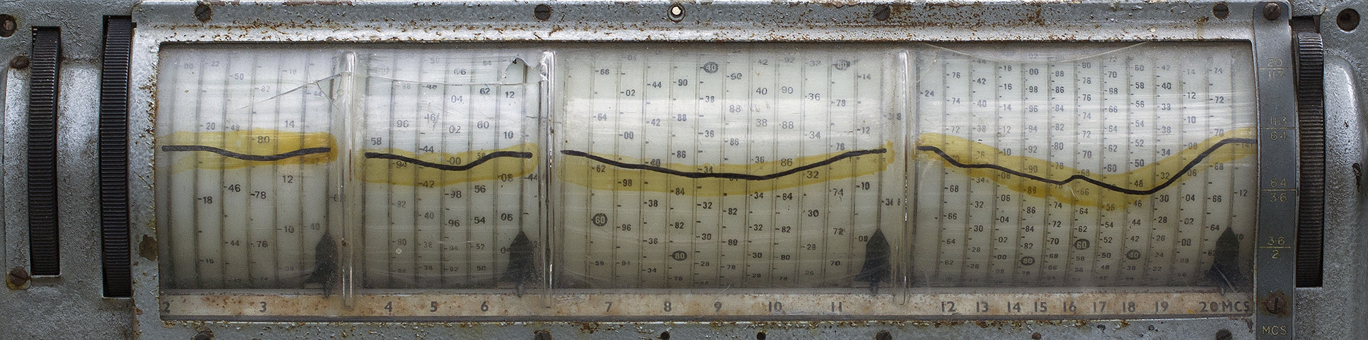
Dating evidence puts the manufacturing date as 1947.
The dial markings at first sight seem puzzling but
each of the four wavebands is stretched over a huge length of
dial with markings on a gentle spiral indicated by the four pointers.
The dark wavy line deals with slight tuning discrepancies.
There are twin tuning knobs (fast and slow) and twiddling
these moves the four pointers. The rightmost vertical knob selects
the desired waveband. |
 |
 |
|
|
 |
After a trial rubbing with Brasso a lot of the
tarnishing disappeared.
Nearly the whole receiver is finished in plating.
 |
|
|
Maybe the first task could be to remove the
front panel and clean it up and make it look presentable?
From the evidence it's possible this example was retrieved
from a house clearance garage and had been modified perhaps as
early as the 1960s before being stood down for something newer..
maybe after it failed. As I recall, lots of radios in my collection
turned out to have nasty faults and were relegated to a loft
by owners rather than disposing of them. Nowadays, let's say
in the last 20 years, old WW2 vintage radios are restored but,
back in the days of a flourishing government service market,
new owners would extensively modify stuff. Once Japanese black
boxes appeared the situation changed for many amateurs and early
equipment was set on one side. Anyway returning to the R1475,
also known, incidentally as a Type 88 Receiver. |
|
The receiver's coverage is in four bands...
2MHz to 3.62MHz (60 inches of dial)
3.58MHz to 6.44MHz (60 inches of dial)
6.38MHz to 11.38MHz (120 inches of dial)
11.24MHz to 20.14MHz (120 inches of dial)
Tuning is carried out via lots of anti-backlash gears
and wavechange via a complicated series of levers. |
Valve line-up as follows:-
V1 RF Amplifier CV1053 (EF39); V2 RF Oscillator CV1932
(L63);
V3 Mixer CV1347 (ECH35);
V4 Guard Channel CV1347 (ECH35); V5 1st IF Amplifier
CV1053 (EF39);
V6 Voltage Stabilizer CV216 (VR150/30);
V7 2nd IF Amplifier CV1053 (EF39); V8 AVC CV587 (DH63);
V9 Detector + BFO CV587 (DH63);
V10 Noise Limiter + AVC delay CV1054 (EB34); V11
AF Amplifier CV587 (DH63);
V12 Audio Power Amplifier CV1932 (L63); V13 Tuning
Indicator CV1103 (Y63).
|
|
Unlike most WW2 or immediate post-war receivers
the R1475 is modular in construction. Modules are plug-in simplifying
repairs (given a set of spare modules)
These are as follows:-
Aerial tuning Unit A (Type 145); RF Amplifier Unit
B (Type 146); Local oscillator Unit C (Type 171);
Mixer Unit D (Type 11); First IF Unit E (Type 37);
Inductance/Condenser Unit F (Type 88);
Second IF Unit G (Type 38); BFO Unit J (Type 170);
Output Unit K (Type 45);
Guard Units P & Q (Type 131 and Type 132).
|
|
|
Power supply requirement is met by a matching
mains/battery PSU (Type 360) which connects to the rear of the
receiver via a 4-pin Jones plug carrying 260V HT and 12V LT.
As is the case with the R1155 the HT supply supplies negative
bias to the receiver and as such the negative feed is not chassis
connected.
If I can find a junk box female Jones socket I can
wire this to my R1155 PSU suitably modified to supply 12v LT.
Alternatively I have a home-brew DST100 PSU which could be suitably
modified for the job. Ideally, long-term I should make a purpose-built
PSU which matches the receiver. |
 |
|
 |
 |
Removing the front panel (above) was quite easy
except for the four pointers dropping off. These locate in slots
in the dial and slide along the bar marked with frequency numbers.
Reassembly might be tricky.. I noticed the row of module sockets
had lots of loose solder joints which I'll have to deal with
before reassembly.
I found I needed to drill the copper rivets holding
the bar carrying the frequency numbering and detach it so cleaning
it was possible and front panel paint removal was easier. Then
I used a steel rule and gentle tapping with a hammer to straighten
the edges of the front panel which had suffered from umpteen
bumps during its life.
The last owner had used a silver crackle effect paint
which was in poor condition. The paint had made the panel labelling
almost disappear so the new paint needs to deal with this problem.
The magic eye panel had shed nearly all its new paint from zero
adherence. |
|
 |
|
It was an incredibly messy task. Removing three
coats of paint (Silver hammerite, some black,and,finally original
grey) using a stripper called TX10 which did what it said on
the tin. Our second recent purchase from Amazon where the package
was found hidden away by the back gate by a visiting lift engineer
who'd spotted it. "Handed over to the occupant" it
said on the on-line delivery info.
No it wasn't...
A few months back I decided to stop using these next
day delivery options as it somehow seemed immoral to abandon
real shops, however I spotted something I needed in Curry's recently..
I went to their store and was told it wasn't in stock but I could
have it delivered within a week for an extra cost.
The panel colour above (tricky to reproduce it here
true) is similar to other (cleaned) metalwork but the bezel has
pinpricks of rust starting at some of the engraving. I might
be able to treat this and rub it down to improve it.
The four handles (made from brass) were covered in
black plastic and this was badly cracked so I removed it. Underneath
was a thick coating of verdigris which I removed with a wire
brush. I suppose I could use heatshrink sleeving rather than
paint?
Then I cleaned up the surround to the plastic dial
which was a bit rusty at the sharp edges. Rubbing down with emery
cloth revealing a thick copper plating underneath. |
|
 |
|
Left is a slightly puzzling control. It connected
to one of the modules but, because it uses stiff wires, one had
broken away and the second looked dodgy, so I opened up the case
and fitted stranded wires. It appears to be a small variable
capacitor but not of standard construction and is labelled "Scale
Trimmer" on the panel.
Below is the megacycle scale which I cleaned up as
much as possible without damaging the lettering. As rust
has taken hold under the label it will have to do. Options are
to remove everything, repaint and either carefully apply lettraset
or make a new lettered strip using handheld label printer. |
 |
|
|
 |
|
Above is a view from the front, clearly less the front
panel, with the various controls, magic eye socket and phone
sockets lying loose, after I'd decided to clean up the metalwork
as best I could. The steel chassis is heavily silver plated and
had badly tarnished but with pock marks of rust present over
most of the metalwork. The latter I had to clean off using small
brass brushes in an electric drill then finish off with Brasso.
The main task is to paint the front panels and other
parts, then I can reassemble everything, figure out what to use
as a power supply then carry out initial testing. I'll also fit
dummy controls for the absent guard receiver to make things half
presentable.
Below, after painting the front panel parts. |
|
 |
|
I now have a dis-assembled
abandoned project so with a fair wind I should be able to
copy parts re the guard receiver whose mechanical mounting bits
are missing. I had intended to use parts from the newly acquired
box of bits but they're too good to scrap. This means I'll have
to make new parts to replace those that are missing, for example
I'm looking at the design of the contact strip to mate up with
the guard receiver contacts plus a new circuit fto fit in the
empty guard chassis that came with this R1475. Below... details
of the guard receiver.
The guard receiver uses a crystal matched to the desired
broadcast channel. This is a large-style FT241. Can I dispense
with this crystal if for example I wish to receive Radio 4 on
198KHz?
I'll need to understand the R1475 local oscillator
circuitry to see what's feasible. |
|
|
|
|
A bad omen... I started to assemble the guard
receiver chassis that came with the disassembled bits from the
second R1475 and had difficulty with fitting the preset capacitors.
After puzzling over this for ten minutes I realized the front
panel could be fitted in four different ways but only two were
possible and in both cases the newly painted surface was on the
inside so I had to respray the metal plate. In fact although
fitting this panel to the chassis looked easy it wasn't due to
the awkward location of the fixing screws. |
 |
 |
 |
 |
|
One tricky bit was the tuning condenser (with the black
knob) which needed to be secured with spacers to push it back
from the panel otherwise the end-stop bracket wasn't in line
with the pointer. A clue (apart from it the end-stop not having
any effect) was one spacer left over in the bag of bits for the
guard receiver.
Once I'd finished reassembly I found it extremely
stiff to fit in the aperture in the main front panel of my first
receiver. Clearly tolerancing was an issue when these receivers
were made.
I also need to make a new front panel to replace the
dummy one that came with my R1475 (at least it came with those
two handles). Also, I need to make a new contact strip.. read
on. |
 |
|
|
 |
 |
|
The housing shown here fastens to the rear of the
front panel and holds at an angle a plastic strip to which is
rivetted a set of spring strips. As the guard receiver pushes
into place sliding over the angled strips to make firm contact
with a set of prongs.
The construction of the new contact assembly needs
to be very accurate if the guard receiver mates up so the contacts
accurately match the spring strips. I have the original chassis
(with no electrical parts) from the assembled R1475 but I need
to make a new front panel as the one fitted is blank. Maybe (if
feasible) I should make the reconstructed guard receiver fit
for something useful such as designing it for a broadcast station..
Radio 4 LW or a strong MW station?
I already reassembled the latest guard receiver, which
at first sight is only missing its front panel (detached for
repaintng by its last owner). This is necessary because I need
to ensure the new contact assembly will work with the other incomplete
guard receiver. |
|
|
 |
 |
 |
Here's a few pictures showing the construction
of the spring terminal strip. I marked out eleven holes on a
scrap piece of bakelite then drilled (using a pillar drill to
keep the holes vertical) and tapped these for 6BA. Fortunately
I had a collection of phosphor bronze strips and used some of
these for the springs. As they took up nearly all the lateral
space I heatshrinked the centre portions and cut a chamfer on
some of the edges to keep them from getting too close. The solder
ends I bent clear. The two longer strips on the right are configured
as a normally made switch and I'll solder a piece of metal from
a scrap relay later. |
|
|
|
|
|
|
|
|
in progress |
|
|


