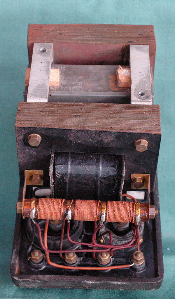
The views above show an
old battery charger/eliminator (covered in half an inch of dust
when I picked it up) which I bought at an Antique Fleamarket
in Antwerp (see also the meters, I got from another stall at
the same place ...elsewhere on this website).
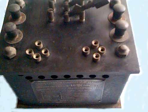
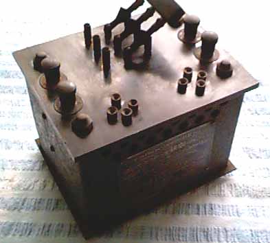
Similar devices to this one
could be used to replace the HT battery in an old radio in the
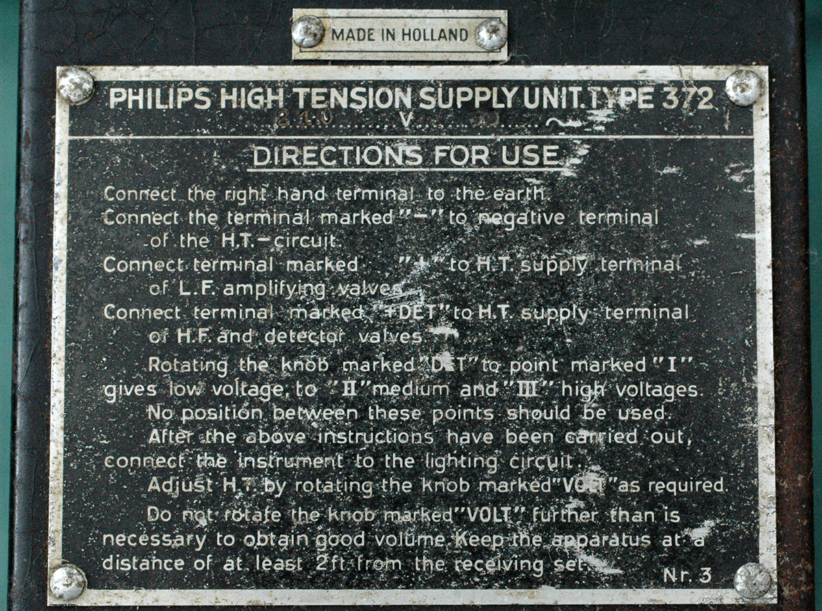
late 20s and early to mid-30s. This one has a nice metal label
which proclaims that it's a "REDRESSEUR DE COURRANT B.B
DEPOSE" for 110 volt 50 Hz mains and provides 40-80-120
volts @ 0.1Amp and and 2 to 12 volts @ 1.3Amp. It originally
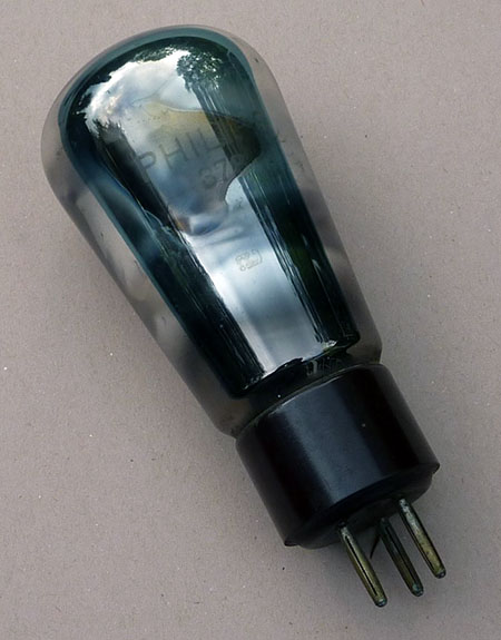
had two Philips tubes, types "1010" and "1011"
fitted in the pair of B4 sockets in the ebonite top. There's
a nice three way knife switch on the top and four screw terminals
for connecting up to the radio. When the switch is one position
an accumulator from 2 to 12 volts may be charged. When in the
other the unit can replace the radio's HT battery (or maybe charge
an HT battery, which were not too common). In the latter position
it's a battery eliminator and in the first it will charge the
filament supply 2 volt accumulator. One cannot do both at the
same time as it explains on the label. I suppose it can also
charge lead acid HT batteries (these were not very common)...maybe
that's it's prime purpose, just charging either battery as it
may be a source of hum without additional components for smoothing?
So, what's the translation
of that label? Redesseur de courrant means "current rectifier"
and B.B deposé stands for "Made by Bayot and Blaimont",
a Belgian manufacturer. The company operated from a factory in
the suburb of Uccle or Ukkel in Brussels.
I couldn't find details of the two valves
in my reference books but Trevor Gale's website gave a query
form and an answer provided the 1010 is a double diode rated
at 60volts, 3.5Amp (some filament emission!) with a filament
supply of 1.8 volts 3.5Amp.
The 1011 wasn't listed but a recent email
from Peter Hughes in Australia has solved the mystery. The 1011
is a curent regulator tube, known as a barretter and the unit
may be a Philips Model "1009".
I wonder if the unit just pre-dated
the disk or electrolytic rectifiers which were available in 1928?
I asked the chap I bought it
from if he knew what it was and he just shrugged but he said
wanted 300BF for it. I offered 200 (£3.50) which he accepted
but I felt very guilty as the smallest I had was a 2000 Franc
note. As I took the very heavy dusty old box, with its mains
lead cut off short and the handful of change in notes. which
he very deliberately counted out, I jokingly asked if it was
guaranteed. He replied after a few seconds of thought (with a
"poker face"), "two years". I found most
Flemish Belgians invariably had that sort of sense of humour.
I was at a small bar in Tournai three months earlier with a couple
of friends and my 14 year old son. We ordered three Jupilers
and asked the barman what he'd recommend for Jeremy. He thought
for a few seconds and said a lot of flemish words then ushered
us back out to a pavement table. Soon he appeared with three
beers and then disappeared back into the bar to reappear. a moment
later, with the same beer but in a glass the size of a thimble.
We proceeded to quench our thirsts (it was very hot) and Jeremy
who looked a bit taken aback sipped daintily at his. After a
few moments there was the sound of merriment inside shortly followed
by the barman who emerged with a tray, on which was a fourth
(normal sized) Jupiler. |