Bird Thruline Wattmeter

I inherited two Bird Model 43 wattmeters. See Manual

 First the two wattmeters before cleaning. The tarnishing on the nickel plating on the left one was also present inside the aperture.

The right hand one looks fine but was giving trouble. Because it hadn't been used for decades the inside of the aperture had a film of greasy dirt which, with the dirty inserts, resulted in poor electrical contact and slight arcing which gave a false meter reading in the reverse power position.

 The important thing about these is they came with a decent selection of plug-in inserts.

Power normally is input from the left. The insert is positioned with the arrow pointing right and the load connected to the right hand socket.

Rotate the insert and the meter will indicate reflected power from the load.

Below is the set of inserts that came with the meters

 Many wattmeters or SWR (Standing Wave Ratio) meters are frequency dependent and the readings you see on their dials is not particularly accurate.

Bird dealt with this by making scores and scores of different plug-in inserts covering a wide frequency range and having different power ratings. The inserts sometimes called "slugs" are coded with a number and letter. As you can see the number is the watts for full scale deflection and the letter indicates the frequency range. As they retail for $100 to $200 my collection is pretty valuable.

Common frequency ranges are coded:- H=2-30MHz; B=50-125MHz; C-100-250MHz; D=200-500MHz; E=400-1000MHz

As I was getting strange results, in particular around 3 or 4 watts of reflected power from one of the meters using the same insert when driving a 50 ohm load I decided to find out why this was.


The left meter has PL259 sockets and the right one N-type sockets.

 The one on the left was OK, giving correct readings, but the one on the right which looked nice and clean had a greasy dirty film around the inside of the hole for the insert.

The inserts don't look too bad but some have ridges of dirt which insulate the insert from the hole and nearly all the metal tabs had raised black nibs, possibly formed by sparking and some that look clean have a greasy film..

 After polishing with Duraglit and cleaning with isopropyl alcohol they look better, notably the pairs of tabs which mate with the metal contact prong in the hole.

Here's a close-up of a typical tab before being polished

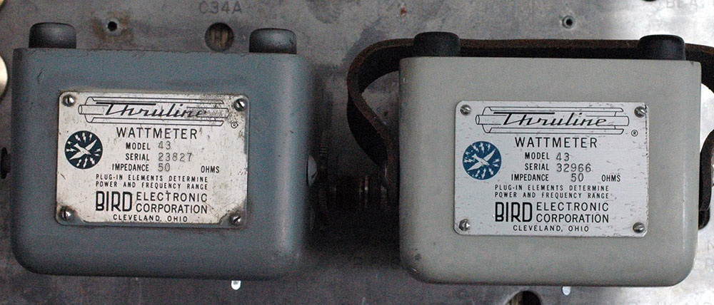
 After cleaning I tested the two meters with the same 100 watt 100-250MHz insert. Running 100 watts into the TF1020A dummy load proved that both meters showed exactly the same results. 100 watts forward power and a just discernible reflected power at 145MHz.

A transmitter is designed to drive its power into a specific load, generally 50 ohms nowadays, but in days of old this may have been 75 ohms or indeed, for example with marine transmitters, hundreds or even thousands of ohms. You can generally tell from the type of output socket what the load should be and in the case of say a Sailor HF transmitter you will see a large porcelain insulator rather than a coax socket. How can you measure the power from this type of transmitter, if it's aerial impedance is a thousand ohms? You certainly cannot readily use a Bird wattmeter. The solution is to insert a hot-wire ammeter in series with the aerial, a method used during WWII for transmitters using wire aerials to help an operator get the best output from his transmitter. Another method, which was used during WWI was to use an absorption wavemeter. By the operator positioning the wavemeter close to the aerial he could tune it so a small lamp lit up to maximum brightness. If the indicated frequency or wavelength, was correct the operator would then re-position the box somewhere convenient (so as not to damage the bulb) and adjust the transmitter for maximum brightness of the lamp.

The Bird Model 43 uses a sensitive microammeter (only 30uA) to indicate forward power and its accuracy is said to be +/-5% and insertion loss only 0.1dB. What does that dB number mean? It sounds really low and hardly worth bothering about, but it means you lose about 2.5Watts from your 100Watts so it's maybe a good idea to remove the wattmeter and gain about 2.5% extra signal. Generally speaking, the cheaper your wattmeter or SWR meter the more the loss is going to be.

Here's a rear view of the pair

Return to Reception