|
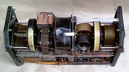
Top view showing the coil
pack with its wavechange switch mounted on the centre metal screening
plate dividing the grid and anode coils. The left side contains
the grid coil with its tuning condenser. Just visible on the
end panel is a tubular device carrying three integral fixed condensers
for allowing different degees of selectivity/sensitivity to be
selected via three aerial sockets. On the left of centre, coloured
black is a large high Q aerial or grid tuning coil of the RF
amplifier. On the right are the anode and grid coils of the second
stage with the tuning condenser. Coupling between the valves
is via the pair of vertically mounted coils, the rear of which
carries a variometer assembly (a pick-up coil which may be moved
mechanically to alter the degree of coupling between two others)
for setting the degree of feedback or regeneration. This is one
of several ways, in those days, of implementing a reaction control.
This inductive technique gives a noise-free infinitely variable
setting. The mechanical control is via a rod passing through
a hole drilled through the centre of the tuning condenser spindle.
Setting of both the large tuning condensers is via slow motion
drives which are integral to the design of the condensers and
offset a few inches from the spindle carrying the condenser vanes.
The tuning scales are fixed to rear projections of the condenser
spindles and are calibrated with the usual 0-180.
The end plates are made of black
bakelite but that on the right is plated on the inside with metal
to minimise hand capacity which would affect stability.
The small pegs around the end
plates are used for accommodating the case screws. |