|
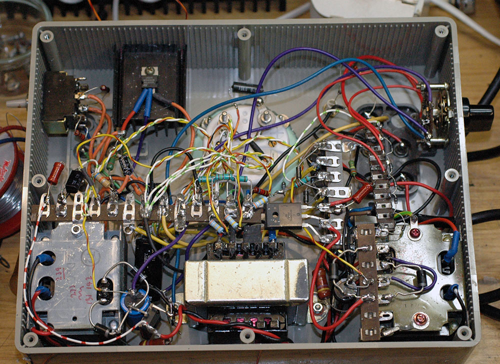
Above you can see the parts used
in the construction. There are three small transformers, all
low voltage types, as its difficult to buy suitable types these
days for HT.
The centre transformer has two 12 volt
windings, one of which drives the two other transformer low voltage
secondaries. If you understand these sort of things you might
be able to work out that the two outer transformers each have
a 110 volt + 110 volt primary and a 12 volt secondary winding.
These deliver, via a full-wave rectifier, suitable DC voltages
for developing the HT outputs I need. I used a fair bit of trial
and error to select suitable transformers from my junk box because
thansformers do not work particularly well when used back-to-front.
Again, if you study the rats nest wiring
you might be able to see the power transistors used in the regulation
circuits. Lots of parts, including most of the tag strips, are
used in the output voltage meter circuits. At the top right is
the HT selector switch which adds or subtracts zener diodes.
All the HT supplies are stabilised.
The LT supplies are derived from an
LM317 regulator (top left) which can provide a decent output
current of better than an amp. Originally I had a variable output
for setting the two voltages, but I discovered that if the pot
was intermittent the output voltage tended to rise intermittently
and this might detroy any 1.4 volt filaments connected to the
output. For the time being I've fitted a three-way toggle switch
which selects either 1.4 volts or 2.0 volts via a pair of resistors
which set the LM317 output. I think it may be better to fit another
terminal so that two rather than a single switchable output is
provided so that there's no chance of inadvertently switching
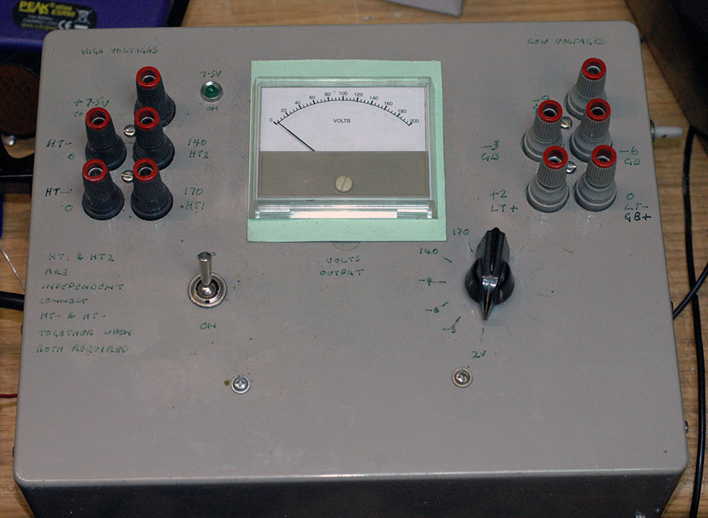
from 1.4 to 2 volts. As an afterthought I also wired out a 7.5
volt output and use this to illuminate the green LED.
Use your browser return to go back to
the page you were reading, or |