The TF1020A and TF1152A
Wattmeters
|
|
I inherited two
of these wattmeters and can't say if they ever worked properly
after the last date on their labels, but it wouldn't surprise
me if they were drummed out of service when they became unreliable.
There are several versions of this useful equipment. Without
the "A" is a 75 ohm version. The 1020 is a high power
model and the 1152 a low power model. Also worth noting is the
fact that there are two versions of the TF1020A. The basic model
with /1 can measure 100 Watts and 50 Watts and the higher power
meter which is coded /5MI (which is mine) and can measure 150
Watts and 300 Watts. It appears that both types use exactly the
same power resistor mounted in a special enclosure which provides
excellent matching up into the UHF region. Both types use a similar
power sensor which provides a small DC voltage which is proportional
to the heating effect of the incoming AC power. In the case of
the higher power meter the sensor is shunted by a 22 ohm resistor
which bypasses about two thirds of the output voltage, leaving
a third driving the metering circuit. The higher power meter
has a mains operated blower for cooling the power resistor.
I spotted a model TF1020A/4MI
on Ebay which was a 75 ohm 150W/300W.
The first picture shows the
complete TF1020A/5MI equipment with base-mounted blower. As my
experiments were initially on this high power model, I'll leave
the low power model till later.. |
 |
|
As you can see there's
no shortage of labels, dating from 1964 to 1992. I particularly
like the one about the RF connector. They even underlined OMHS.
Does the anchor label mean it
was owned by the Royal Navy? I guess not as a rear seal plainly
mentions RAF. |
 |
|
The instrument has a large
50 ohm resistor with a working length of about 20cm, tapped at
2cm and wired to a metering circuit using a thermal sensor.
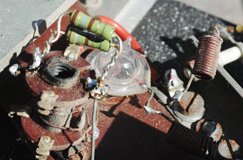
Firstly the parts that drive
the meter on the front panel. The sampling connection at the
50 ohm dummy load is a metal band set at about 5 ohms from ground
which connects via a 220 ohm resistor in series with a small
coil having about 4 turns tuned by a dust core. The coil connects
to ground via a 22 ohm resistor and also connects through the
glass encapsulated device to ground. This device is a thermal
sensor and has two output wires, one of which is connected to
ground via a 15 turn high frequency choke and the other via a
similar choke to the meter circuit. These will have an inductance
of around half a microhenry. Two adjusting pots and a selection
switch connect the meter to either the sensor choke or to the
sensor choke via an additional 5 ohm wirewound resistor mounted
across a small grey coloured component, probably a VDR.
The monitoring circuit is therefore
a potential divider feeding the thermal sensor which connects
to the meter via two switchable circuits. One circuit connects
directly to the thermal sensor and the second to the thermal
sensor plus a 5 ohm resistor. The meter is marked 850uA and the
two potentiometers for setting the scale accuracy are low value
wirewound devices of 25 ohms for the 150W range and 10 ohms for
the 300W range. I suppose the coil in the potential divider will
increase the impedance of the leg carrying the 220 ohm resistor
as the input frequency increases. From the table above, if this
coil is 0.5uH it will add an extra 300 ohms at 100MHz, however
this ignores the capacity of the circuit and in reality the coil
will act as a resonator with stray capacity to maintain the voltage
divider accuracy at higher frequencies. From the table above
a stray capacity of around 3pF will resonate the coil at something
over 100MHz. This coil can be preset as it has an adjustable
core. The RF chokes will stop stray RF from getting into the
meter circuit.
Interestingly the wattmeter
will work at DC and at 50Hz as well as at radio frequencies.
If 100 volts DC is applied across the input socket you will draw
a current of 2 Amps through the 50 ohm resistor dissipating 200
watts. At the tapping point there will be a voltage of 10 volts.
This voltage feeds the sensor
circuit divider whose output voltage is (220+22)/220=1.1 volts.
The resistor tolerances are 2% for the 220 ohm and 5% for the
22 ohm making the output 1.09 to 1.103 volts. This is applied
to the thermal sensor for which I don't have a spec sheet. However,
if the output from the sensor is say 0.1 volt this will feed
the 830uA meter via the circuit resistances. If these, including
the meter resistance are 125 ohms. the current will be 660uA.
Having worked out the circuit
I did some more tests.
Firstly, the two potentiometers
for adjusting the meter readings were poor. Although the tracks
looked pristine the end readings were bad, intermittently showing
a few ohms instead of zero, but by using the resistance range
in the centre of travel they were OK. The fact that only an extra
5 ohms is used to double the power reading is interesting. The
implication is that the pots will have a fairly coarse effect
on the readings (and this is what I discovered later).
Initially I connected an external
power supply (actually several small supplies in series) and
set the voltage to 100 volts. This drew 2 amps through the 50
ohm load resistor and I expected to see 200 watts indicated,
however the indication was only 87 watts. I then set the voltage
to read 70.7 volts which should register 100 watts on the meter.
The meter showed 50 watts. I then connected a small pot across
the 220 ohm divider resistor and adjusted it so the meter read
100 watts with RV2 set half way to avoid the rough end track.
This divider modification increases the voltage across the sensor.
Disconnecting the pot revealed
it was set to 218 ohms so I fitted a 220 ohm resistor across
the existing 220 ohms. Setting the input voltage again to 70.7
volts gave me around 85 watts on the meter, but adjusting RV2
gave me exactly 100 watts. Clearly the difference of only 4 ohms
has a significant affect on the readings. Switching to the 300
watt range, I set RV1 to read 100 watts. The instrument should
now read RF power correctly on both ranges.
What was the problem? Well without
details for the thermal sensor it's difficult to say exactly,
but the instrument was reading low. The original 220 ohm divider
resistor was indeed 220 ohms so it wasn't that. It's possible
the 22 ohm resistor had gone low? It's also possible the 850uA
meter is faulty?
I'll try the wattmeter now that
it's modified and see if it's stable. |
 |
Below.. the thermal sensor
looking a bit like a 955 triode
I found this information about the thermocouple
Ultra High Frequency, Vacuum
Thermo-couple, Insulated to 100V DC, Heater Current range 25ma,
Max overload 37.5ma
Heater resistance 25 Ohms, Couple Resistance 3-4 Ohms, Couple
output 16-20ma
Ormandy & Stollery LTD.
3 Victoria Place
Brightlingsea
England |
 |
|
Below is a circuit diagram
of the TF1020A found by Fred, VK2FM |
 |
|
View of the load resistor
in a shaped aluminium enclosure for matching. |
 |
|
Looking down the load
resistor to the tapping point |
 |
|
Load resistor clamped
at earthy end showing tap for sensor |
 |
|
Next, I need to test the
wattmeter to see if the settings have changed and then to confirm
that it responds to RF power in the same way as DC.
I'd also like to see what its
frequency response is like to see if it meets its spec of DC
to 250MHz. The mechanical design is rather strange and I guess
this is to make its response to RF more or less uniform. At the
lower end of the load resistor the aluminium screen is very close
to the surface of the carbon surface and bracing strips imply
the shaping is pretty important.
First power up the wattmeter
with 70 volts DC. Read slightly low so twiddled RV2 to read exactly
100watts.
Hooked up the 2 meter transceiver,
an FT480 + Microwave Modules linear and saw the Bird Model 43
meter reading 100watts but the TF1020A read only about 35 watts
or so. RV2 couldn't reach anything better than this so either
the wattmeter is reading RF differently to DC or the Bird wattmeter
is very optimistic.
Here are the pictures of the
experiment |
DC TESTS
|
 DC power reading=100 watts...
 |

at 71 volts |
|
Current at 71 volts is
1.45 Amps= 103watts
|
 |
RF TESTS
|
|
Linear amplifier output
100 watts |
 |
At 145MHz
|
 |
|
And the TF1020A reads
about 35 watts (At least it's better than the 25 watts before
I modified the TF1020A) |
 |
|
and reverse power from
mismatching about 20 watts. |
 |
|
Could the Bird wattmeter
be reading too high as 20 watts of relected power seems too much?
I have two of these so I swapped
them over using the same insert which is 100MHz to 250MHz 100Watts
This time I got 90 watts forward
and zero watts reverse instead of 100 watts forward and 20 watts
reverse (the first Bird Wattmeter proved
faulty and worked normally after repair).
The TF1020A read 42 watts. This
is getting odder and odder. Admittedly I changed the various
interconnecting cables and adaptors because the first Bird uses
PL259 and the second N-type. Could the anomalies be partly due
to a faulty cable? |
AC Tests
|
|
As there are several possible
reasons for the power reading discrepancy including the response
of the TF1020A to VHF, I decided to test it with a low frequency.
The simplest of course is a test at 50Hz so I found a few low
voltage mains transformers and connected these to my variac so
that I could easily alter the output voltage. Because the windings
are connected in series one needs to get the phasing right. If
two windings, say each of 12 volts are connected in series the
result could either be 24 volts or zero, so by trial and error
with the transformers powered up I arranged the output voltage
to be the sum of the windings. I used two 14 volt windings and
a 24 volt winding plus a 36 volt winding to produce about 88
volts. One connection was made to the centre pin of the N-connector
and the other to the chassis of the wattmeter. Now by adjusting
the variac I could set the reading on the wattmeter to conform
to powers up to 154 watts.
The first check I made was 100
watts, setting the input voltage to 70.7 volts on an RMS reading
voltmeter. Having set the wattmeter to work correctly on DC I
expected it to work on 50Hz but alas it did not. The reading
was low. Having already learned that the resistor feeding the
thermal sensor has a significant effect on dial reading I connected
a 5kohm pot across it and carefully reduced its value until I
got 100 watts on the scale. Finding the resistance of the pot
was around 490 ohms, I substituted for the original 220 ohms
plus the 220 ohms dictated by DC tests, a new resistor combination
of two 180 ohms in parallel=90 ohms. RV2 needed tweaking slightly
to adjust the dial reading to exactly 100 watts with 70.7 volts
AC input because 90 ohms wasn't the precise value required..
Summarising: the original resistor
was 220 ohms, the resistor for accurate DC was 110 ohms, the
resistor for accurate 50Hz was 90 ohms.
Because there's a 22 ohm resistor
across the sensor the potential divider outputs for the resistor
combinations are 0.091; 0.166 and 0.196 or expressed as percentage
power available at the load resistor tap, 9.1%, 16.6% and 19.6%.
This means that the power sensor now needs twice the power input
to give the same power reading since its last pass date.
Now, I needed to know if the
linearity of the wattmeter scale was OK. Setting the variac to
supply 40 volts resulted in a scale reading of 32 watts, 50 volts
gave me 50 watts, 60 volts gave me 71 watts and 80 volts gave
me 128 watts. These are all fine so the sensor is supplying good
outputs at all the power inputs tried.
Next, I switched to the 300
watt range, and after adjusting RV1 all power readings were consistent.
Next, I connected 100 watts
of 145MHz to the N-connector hoping to see a scale reading of
100 watts. Instead it read 45 watts.
Now this isn't as bad as it sounds if expressed in dB. If the
wattmeter is specified at around 120MHz or so at -3dB then 45
watts is about -3.5dB which would be about right, however I understood
the wattmeter was good to 250MHz not 120MHz. I decided to measure
the SWR of the wattmeter as this should give an indication of
it spec falling off at higher frequencies. |
New resistors. The 22
ohm resistor shunting the sensor is underneath
|
 |
SWR Measurements
|
To make SWR measurements
you need to measure the forward and reflected power into the
50 ohm dummy load within the wattmeter. To do this I used a Bird
Model 43 wattmeter. I have two of these, and one had been giving
odd results so I fitted the plug-in insert to the good one and
got 100 watts from my linear at 145 MHz with only a tiny reflected
power. Before the reflected power had been too high to make sense.
To be more certain of the results I used a Welz dummy load specified
at 150MHz to compare with results from the TF1020A.
144MHz: Welz 1.43, TF1020A 1.15
145MHz: Welz 1.40, TF1020A 1.16
146MHz: Welz 1.38, TG1020A 1.17
These results are exactly as
one would expect if the TF1020A is indeed specified better than
the Welz.
Could it be possible then that
the TF1020A is an excellent dummy load for VHF, but as an accurate
wattmeter only accurate to say 100MHz and beyond this only good
for comparative measurements such as tuning up a transmitter?
Next, I'll need to carry out
tests at HF and sort out a couple of anomalies, one of which
appears to be an intermittent toggle switch. This is the switch
selecting 150 or 300 watts which sometimes does not cleanly operate
because it's wetting current is less than half a milliamp..
Both potential problems were
resolved. The switch was fine and the 850uA meter read 860uA
full scale deflection.
I then hooked up a TRIO TS120S
transceiver via a Heathkit HF SWR/Power meter to the TF1020A.
Switched to CW and adjusting the carrier control enabled me to
see exactly 100 watts on the Heathkit meter and an identical
reading on the TF1020A, initially on 3.5MHz then on 7MHz, 14MHz,
21MHz and 29MHz. So the TF1020a appears to be working OK at HF.
There's a small tunable coil in series with the TF1020A sensor
potential divider and I guess this can be used to peak the drive
to the sensor at the point where its sensitivity starts to drop
off, but from the measurements I made this must be around 100MHz?
The tests were useful as I now
know the limitations of the TF1020A and its a jolly good dummy
load. Mounted on the underside of the wattmeter is a mains driven
cooling fan so if I need to carry out extended testing this can
be used to keep the wattmeter cool. |
View showing blower
|
 |
|
and underside |
 |
Before
ending here's a picture of my TF1152.
|
 |
|
As you can see this
is a TF1152A/1 and can measure power in two ranges viz. up to
10 watts and up to 25watts.
Later I'll open it up and inspect
the interior then carry out some tests to determine it's accuracy |